Table of Contents
Advertisement
Quick Links
Advertisement
Table of Contents

Related Manuals for Gewiss CHORUS GW 90 872A


Summary of Contents for Gewiss CHORUS GW 90 872A
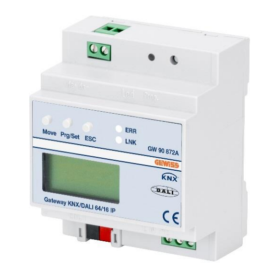
- Page 1 Gateway KNX/DALI 64/16 - for guide DIN GW 90 872A Technical Manual...
-
Page 2: Table Of Contents
Content 1. Using the application program……………………………………………………....………………. 2. General product information........................2.1 DALI Bus system properties..................... 2.2 GW90872A product features…..................3. General properties of the ETS application program: GW90872A Plug-In…….....…………………… 3.1 Installing the Plug-In…………………………………………………………………...……………..3.2 Principal structure of the Plug-In………………………………………………………...………… 3.3 Operating modes of the Plug-In: DALI commissioning…………………………………………. 4. - Page 3 9.7 Burn-in mode …………………………………………………………………………………………..…. 9.8 Operating mode hierarchy ……………………………………………………………………………… 10. Analysis and service functions …………………………………………………………………………………. 10.1 Recording operating hours ………………………………………………………………………….. 10.2 Individual fault recognition at ECG level ………………………………………………………….. 10.3 Fault analysis at group level ……………………………………………………………………..10.4 Fault analysis at device level ………………………………………………………………………... 11.
-
Page 4: Using The Application Program
(in accordance with EN 62386-103). This means Product type: Gateway the device must only be used in DALI segments with GEWISS S.p.A. Manufacturer: connected ECGs and not with other DALI control devices within the segment (no multi-master function). GATEWAY KNX/DALI... -
Page 5: General Properties Of The Ets Application Program: Gw90872A Plug-In
Please check the GW90872A software license ● Scene module for extensive scene programming of conditions before you start the installation. With the groups and individual ECGs installation you accept the conditions. ● Effect module for sequence control and light effects ●... -
Page 6: Operating Modes Of The Plug-In: Dali Commissioning
The choice of the commissioning concept depends on the preferences of the system integrator as well as the technical requirements of the project. If you choose op- tion A ‘Normal Mode‘ the DALI configuration and com- missioning must be performed via the website of the device. -
Page 7: Dali Commissioning
4. DALI commissioning and - if required - assign them to groups. Identification and group assignment can also be performed via the device itself (pushbuttons, display) or via the website. If As explained above, the work flow for the commissioning you use the website for identification, you can give each of a DALI segment differs depending on the selected ECG an individual name (e.g. -
Page 8: Display And Push-Button Control
Use the sub-menu to active the ECG quick ex- cal installation is complete, the actual DALI commission- change function and possibly program and inte- ing can also be performed with ETS. grate individually replaced ECGs into the sys- tem. The first thing to do is to start the teach-in process. Dur- ing this process all connected DALI ECGs are automati- GROUP Use the sub-menu to identify ECGs and assign... - Page 9 ess, the number of newly found devices is shown on the display. Sub-menu NETWORK IP_ADDRESS – Level 2 and 3 Once the whole process (verification and DEL./NEW search) is complete, the display shows both NETWORK ECGs: 3/1 Briefly press the Prg/Set button to change the deleted and the newly found ECGs (de- IP ADDRESS from the main menu IP ADDRESS to the sub-...
- Page 10 Hold the Prg/Set button to change into pro- the ESC button (or wait for about 30 seconds) gramming mode. Briefly press the MOVE but- to return to the level above. ton again to select the group that you want to ECG No.: 12 assign the ECG to.
-
Page 11: Control Via Web Browser
RESET, BURN-IN/RESET. Briefly press the assign an IP address to the GW90872A to enable Prg/Set button to execute the selected com- ECG No.: 01 access via the web browser. By default, all GEWISS mand. Press the ESC button (or wait for BURNIN/RES. -
Page 12: Configuration Buttons
rights are required. The images and descriptions below are all based on the administrator display. Different passwords for user and administrator can be set in the ETS. The default setting for both users is ‘0‘. Log in as administrator to access the following configura- tion website: 6.1 Configuration buttons The icons in the website header are used for the differ-... -
Page 13: Control Buttons
Assign a group ECG Quick Exchange Use this button to assign an ECG to a group. First select Press this button to start an ECG quick exchange within the button. Then click on the group. To complete the process click on the ECG you want to assign to the the DALI segment. -
Page 14: Ecg Fields
6.3 ECG fields ECG in use for individual control The ECG and group entries on the website mean that the user can see the complete function and failure status of a connected DALI segment at a glance. The ECG fields are numbered from 1 – 64. The number is shown ECG with group assignment (e.g. - Page 15 To display the status information of a group, click on one An ICON appears behind the word Mode if the ECG is of the 16 group fields. not in normal mode. The meaning of the icons is as follows: Permanent mode Panic mode Central battery test mode Burn-in mode...
- Page 16 This display shows the type of test, test result and date and time of the last test. The status bar shows the failure flags. A green bar means that the test was positive. A red bar signals a negative test result. You can use the buttons on this page to manually start a test (Execute Test).
-
Page 17: Ets Special And Commissioning Functions
7. ETS special and commissioning functions As previously described in chapter 4, you can choose eiher type A ‘Normal mode‘ or type B ‘Extended mode‘ for the DALI commissioning. Depending on the mode you choose, different special functions and pages are available in the ETS. -
Page 18: User-Friendly Names For Ecgs And Groups
The synchronisation compares the application to the As loading the names via KNX can take quite some time, you should use the Ethernet connection for this process. data of the connected DALI segment. This means that Before starting the process, please make sure you set you should always synchronise when you change the right IP address and tick the check-box in front of the the system structure or expand the system. -
Page 19: Preparation And Planning The Dali Commissioning In 'Extended Mode
7.2.1 Preparing and planning the DALI commission- the first ten characters of the name entered in the plug- ing in ‘Extended Mode‘ If you confirm your entry with the return button, the cur- sor automatically jumps to the next ECG field. This In Mode B, the menu item ‘Commissioning‘... -
Page 20: Dali Commissioning In 'Extended Mode
been assigned to a group are automatically regarded as ECGs for individual control. Please see chapter 11 for the planning and setting of scenes and effects. 7.2.2 DALI commissioning in ‘Extended Mode‘ Once the planning, parameter setting and linking of group addresses have all been completed the DALI segment can be commissioned. -
Page 21: Ecg And Lamp Faults During Dali Commissioning In 'Extended Mode
If an ECG has been wrongly assigned, it can be moved the actual ETS application with parameter settings back to the list of non-identified devices using the same and group addresses still has to be downloaded drag& drop mechanism. onto the device. After leaving the parameter page, this is done via the usual ETS download process. -
Page 22: Using Dummy Ecgs In 'Extended Mode
7.2.4 Using dummy ECGs in ‘Extended Mode‘ downloaded, the gateway assumes that an ECG exists and therefore presents an ECG fault in the visualisation and the respective communication object. There may be cases in which a DALI installation or a DALI segment needs to be commissioned even if not all of the planned lights are yet physically present (e.g. -
Page 23: Parameter Templates
If the IP communications box is ticked but an IP connec- tion is not possible (wrong IP address, no network con- 7.3.3 DALI configuration data back-up nection), the plug-in will still try to make the connection via IP. However, it recognises by itself that this is not The configuration data and parameters set in the ETS possible and automatically changes to KNX communica- are automatically saved in the ETS database after each... -
Page 24: Dali Maintenance And Expansion
8. DALI maintenance and expansion at the end. (Attention: Please remember that the max (Attention: Please remember that the max (Attention: Please remember that the max (Attention: Please remember that the maxi- i- i- i- mum number of ECGs within a segmen mum number of ECGs within a segment is 64!) mum number of ECGs within a segmen mum number of ECGs within a segmen... -
Page 25: Different Operating Modes
9. Different operating modes 9.4 Night-time mode 9.1 Normal mode Night-time mode is available both at group and ECG level. The night-time mode corresponds largely to the In normal mode, ECGs can be dimmed and switched staircase mode. The only difference is that the automatic without restrictions both via individual and group control. -
Page 26: Operating Mode Hierarchy
carried automatically with the highest priority. If an ECG is in burn-in mode, it can- GW90872A. Each ECG can be individually set to the not be changed into any other mode. The next hierarchy burn-in mode via a further object. During the burn-in, level is the central battery test mode. -
Page 27: Analysis And Service Functions
10. Analysis and service functions 10.1 Recording operating hours The GW90872A allows for the operating hours (burn-ing time) of each lamp to be internally recorded to the second. The value is available externally (communica- tion objects, web site, display on the device) in hours with the internal value in seconds always being rounded. -
Page 28: Fault Analysis At Device Level
11. Scenes and effects 10.4 Fault analysis at device level 11.1 The scenes module Fault analysis objects similar to those at group level are The GW90872A enables the programming and in-voking also available at device level (i.e. for all ECGs connected to the gateway). -
Page 29: Scene Programming Via The Scene Website
time of 20 seconds, the dimming process takes only 10 ously programmed, the corresponding light value ap- seconds. pears). Once you have selected a scene, you can use the as- signment button to add or remove groups or individual Switching an individual group (or ECG) from the scene ECGs to and from the scene. -
Page 30: The Effect Module
field in the middle using drag-and-drop. Use the value fields to enter the light value for this scene. You can enter a user-friendly name for each scene in the description field underneath the scenes. If you do not want a scene to start immediately but would prefer dim- ming it up to its final value (see above), you can set the dimming time individually for each scene. -
Page 31: Effect Programming Via Ets In 'Extended Mode
Effect programming Please remember that the set values are only saved if you press the button. If you change to another effect without saving, any changes you made are lost. Use the Start and Stop buttons to activate and test the selected effect directly from the page. -
Page 32: Self-Contained Battery Emergency Lamps
12. Self-contained battery emergency lamps the connected lamp themselves, the normal identification process through switch on/ switch off is not possible. The identification therefore needs to occur via the LED. The GW90872A supports control gears used to run self-contained battery emergency lights (device type 1 in accordance with EN 62386-202). -
Page 33: Ets Communication Objects Overview
Alternatively, or in addition to reporting via communica- tions objects to the bus, test results can be displayed on the website if you select the respective converter. Object name Function Type Flags Broadcast, On/Off 1 Bit Switching DPT: This object is used to switch all connected lights on or off. However, any connected ECGs that are in special mode (Burn-In, Emergency Test, Panic Mode) are not switched and the DALI bus is addressed sequentially. - Page 34 Activate Night Activate / 1 Bit General Failure Value 1 Byte Mode Stop in % This object is used to activate or stop the night-time mode Alternatively, this object is used to report the failure rate as via the bus. a percentage of the total number of devices in the DALI segment.
- Page 35 Status Status 8 Bit Failure Status Status 8 Bit Switching Lamp Lamp/ECG This object is used to send the switch status of individual This object is used to send the failure status of lamp or lamps in the DALI segment when the system is started or ECG failures in the DALI segment when the system is when a change has taken place.
-
Page 36: Ecg-Related Communication Objects
13.2 ECG-related communication objects This object is used to send the ECG switch status. Any value >0% is interpreted as ON. ECG1, Status Value 8 Bit A set of 11 communication objects is available for each one of the up to 64 connected ECGs / converters and corresponding lamps. -
Page 37: Group-Related Communication Objects
Object name Function Type Flags Object name Function Type Flags Converter 1, Start 1 Byte CW Test Start Group 1, On/Off 1 Bit Switching This object is used to start a long duration test, functional test and battery test of the converter. The individual Bits This object is used to switch group 1 on or off. -
Page 38: Ets Parameter Overview
Group 1, Status 1 Byte CRT 14.1 Device: General Settings Failure Status This object is used to send the failure status for lamp, ECG and converter failures within the group as a 1Byte object. Bit 0 Lamp failure Bit 1 ECG failure Bit 2 Converter failure... -
Page 39: Parameter Page: Ip Settings
14.1.2 Parameter page: IP Settings Light Status Send Condi- Send on Request tion Send on Change Send on Change and after Busreset Parameter Settings Use this parameter to determine the light status send con- IP Address (byte 1) ditions (switch status and value status) of the connected ECGs and groups. -
Page 40: Parameter Page: Special Functions
Behaviour after Panic / Switch to Off-Value Cycle Time for DALI Fail- No Delay Emergency Mode ure request Switch to On-Value 0,5 Seconds Switch to Last Value 1 Second 2 Seconds Use this parameter to set the light value of ECGs / lamps after the panic/emergency mode has finished. -
Page 41: Ecg No
Threshold for Converter Emergency Luminaire with No Emergency Luminaire Failures Central Battery Central Battery Emergency Luminaire Use this parameter to set whether the ECG controls an ….. emergency luminaire with central battery. Devices regis- 100% tered as emergency luminaires are specifically marked Use this parameter to set a threshold value for the con- during status reports. -
Page 42: Parameter Page: Emergency Settings
Operating Mode Normal Mode Delay on Mains Recovery No Delay Permanent Mode 30 Seconds Normal / Night Mode 1 Minute 2 Minutes Use this parameter to select the operating mode of the ECG. 3 Minutes 4 Minutes Value in Permanent Mode 1..100% [50%] 5 Minutes 10 Minutes... -
Page 43: Parameter Page: Analysis And Service
Switch-On Behaviour Set Value Immediately Use this parameter to configure the maximum dim value that can be set through relative dimming. Dim to Value in 10s Dim to Value in 20s Min. Value for Dimming Dim to Value in 30s Dim to Value in 1 Minute …. -
Page 44: Parameter Page: Group No
Function of Additional No Object Object Disable Object Release Object Disable Staircase Function Object Use this parameter to set the function of an additional ob- ject. Enabled for Emergency / Panic Mode Use this parameter to enable a group for panic/emergency mode. -
Page 45: Parameter Page: Analysis And Service
Use this parameter to set the switch-off behavior. Use this parameter to select whether you would like to use the additional failure object as a 1 Byte object for failure number /rate or as a 1 Bit object for when the failure Value-Set Behaviour Set Value Immediately threshold is exceeded. -
Page 46: Firmware Version And Update
15. Firmware version and update more details regarding this process, please see the ap- plication note (pdf format) included with the update. The firmware version of the DALI gateway is divided into main number, sub-number and revision number (e.g. 16. Reset to conditions at delivery 1.0_10).
Need help?
Do you have a question about the CHORUS GW 90 872A and is the answer not in the manual?
Questions and answers