Table of Contents
Advertisement
Quick Links
TopPage
In the interests of user-safety the oven should be restored to its original condition and only parts identical to those
specified should be used.
CHAPTER 1. BEFORE SERVICING
CHAPTER 2. WARNING TO SERVICE PERSONNEL
CHAPTER 3. PRODUCT SPECIFICATIONS
CHAPTER 4. APPEARANCE VIEW
CHAPTER 5. OPERATION SEQUENCE
CHAPTER 6. FUNCTION OF IMPORTANT COMPO-
NENTS
CHAPTER 7. TROUBLESHOOTING GUIDE
CHAPTER 8. TEST PROCEDURES
CHAPTER 9. TOUCH CONTROL PANEL ASSEMBLY
SERVICE MANUAL
MODEL
CONTENTS
CHAPTER 10. PRECAUTIONS FOR USING LEAD-
FREE SOLDER
CHAPTER 11. COMPONENT REPLACEMENT AND
ADJUSTMENT PROCEDURE
CHAPTER 12. MICROWAVE MEASUREMENT
CHAPTER 13. TEST DATA AT A GLANCE
CHAPTER 14. CIRCUIT DIAGRAMS
Parts List
S9905R26STPHA
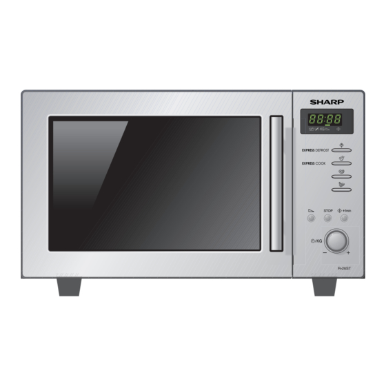
MICROWAVE OVEN
R-26ST-A
This document has been published to be used for
after sales service only.
The contents are subject to change without notice.
R26STA
Advertisement
Table of Contents

Related Manuals for Sharp R-26ST-A


Summary of Contents for Sharp R-26ST-A
- Page 1 TopPage R26STA SERVICE MANUAL S9905R26STPHA MICROWAVE OVEN R-26ST-A MODEL In the interests of user-safety the oven should be restored to its original condition and only parts identical to those specified should be used. CONTENTS CHAPTER 1. BEFORE SERVICING CHAPTER 10. PRECAUTIONS FOR USING LEAD- FREE SOLDER CHAPTER 2.
-
Page 2: Table Of Contents
CONTENTS CHAPTER 1. BEFORE SERVICING CHAPTER 9. TOUCH CONTROL PANEL ASSEM- GENERAL IMPORTANT INFORMA- TION ............1-1 OUTLINE OF TOUCH CONTROL PAN- WARNING........... 1-1 EL ............... 9-1 CAUTION MICROWAVE RADIATION ..1-2 SERVICING FOR TOUCH CONTROL PANEL ........... - Page 3 R26STA R26STA 1 – 1...
- Page 4 R26STA [3] CAUTION MICROWAVE RADIATION Personnel should not be exposed to the microwave energy which may radiate from the magnetron or other microwave generating devices if it is improperly used or connected. All input and output microwave connections, waveguides, flanges and gaskets must be secured.
- Page 5 R26STA R26STA 2 – 1...
- Page 6 R26STA 2 – 2...
- Page 7 R26STA 2 – 3...
- Page 8 R26STA R26STA 3 – 1...
- Page 9 R26STA R26STA 4 – 1...
- Page 10 R26STA R26STA 5 – 1...
- Page 11 R26STA R26STA 6 – 1...
- Page 12 R26STA R26STA 7 – 1...
- Page 13 R26STA R26STA 8 – 1...
-
Page 14: Asymmetric Rectifier
R26STA 1000g 1000g 1000g T1 C T2 C Heat up for 55 sec. [2] B: HIGH VOLTAGE TRANSFORMER (T) TEST WARNING: High voltages and large currents are present at the secondary winding and filament winding of the power transformer. It is very dangerous to work near this part when the oven is on. -
Page 15: E: Switch (Sw1, Sw2, Sw3) Test
R26STA [5] E: SWITCH (SW1, SW2, SW3) TEST CARRY OUT 3D CHECKS. Isolate the switch to be tested and using an ohmmeter check between the terminals as described in the following table. Table: Terminal Connection of Switch Plunger Operation COM to NO COM to NC COM;... -
Page 16: J: Touch Control Panel Assembly Test
R26STA [10] J: TOUCH CONTROL PANEL ASSEMBLY TEST The touch control panel consists of circuits including semiconductors such as LSI, ICs, etc. Therefore, unlike conventional microwave ovens, proper maintenance cannot be performed with only a voltmeter and ohmmeter. In this service manual, the touch control panel assembly is divided into two units, Control Unit and Switch Unit, and also the Control Unit is divided into two units, CPU Unit and Power Unit, and troubleshooting by unit replace- ment is described according to the symptoms indicated. -
Page 17: M: Procedures To The Control Unit
R26STA Check voltage at the relay coil with a D.C. voltmeter during the microwave cooking operation. DC. voltage indicated ........Defective relay. DC. voltage not indicated ......Check diode which is connected to the relay coil. If diode is good, control unit is defective. RELAY SYMBOL OPERATIONAL VOLTAGE CONNECTED COMPONENTS... - Page 18 R26STA R26STA 9 – 1...
- Page 19 R26STA it apart from the oven proper; in this case you must short both ends of the door sensing switch (on PWB) of the touch control panel with a jumper, which brings about an opera- tional state that is equivalent to the oven door being closed. As for the sensor-related controls of the touch control panel, checking them is possible if the dummy resistor(s) with resis- tance equal to that of the controls are used.
- Page 20 R26STA R26STA 10 – 1...
- Page 21 R26STA R26STA 11 – 1...
-
Page 22: High Voltage Transformer Removal
[7] TURNTABLE MOTOR REMOVAL 1. REMOVAL 4. Where the corners have been snipped off bend corner areas flat. No sharp edges must be evident after removal of the turntable 1. Disconnect the power supply cord. motor cover. 2. Remove turntable and turntable support from oven cavity. -
Page 23: Cooling Fan Motor Removal
R26STA 7. Remove the TTM packing from the turntable motor. 5. Re-install the turntable motor cover to the bottom plate with one (1) screw. 8. Now, the turntable motor is free. TTM packing 2. REINSTALL 1. Re-install the TTM packing to the turntable motor. 2. -
Page 24: Control Panel Assembly Removal
R26STA Power Supply Oven Cavity P ower S upply Cord Back Plate Screw C ord Moulding C ord S topper Brown Wire Green/Yellow Oven C avity Wire B ack P late Blue Wire S quare Hole Noise Filter Figure C-3(a) Power Supply Cord Replacement Figure C-3(a) Figure C-3(b) Power Supply Cord Replacement [10] CONTROL PANEL ASSEMBLY REMOVAL 1. -
Page 25: Door Replacement
R26STA [13] DOOR REPLACEMENT 1. REMOVAL 6. Catch two (2) pins of door panel on two (2) hole of upper and lower oven hinges 1. Disconnect the power supply cord. 7. Re-install choke cover to door panel by pushing. 2. Open the door slightly. NOTE: After any service to the door;... - Page 26 R26STA R26STA 12 – 1...
- Page 27 R26STA R26STA 13 – 1...
- Page 28 R26STA R26STA 14 – 1...
- Page 29 R26STA SCHEMATIC NOTE: CONDITION OF OVEN 1. DOOR CLOSED. 2. PLUGGED IN OVEN. 3. DOOR OPENED AND CLOSED. 4. “ . 0” APPEARS ON DISPLAY. NOTE: " " indicates components with potentials above 250V TEMP FUSE MG: MAGNETRON T: HIGH VOLTAGE CONTROL UNIT TRANSFORMER FUSE 2.5A...
- Page 30 Power Supply Oven Cavity Screw Cord Back Plate SW3: DOOR SENSING CONTROL PANEL SWITCH F1: FUSE LIVE TEMPERATURE N.O. FUSE (OVEN) (SWITCH UNIT) (POWER UNIT) CN-B WH-A NEUTRAL CN-G Noise Filter WH-B CN-H CN-B FM: FAN MOTOR CN-A 7 BLK 5 ORG OL: OVEN LAMP 3 WHT...
- Page 31 CN-H B7B-PH-K-S(LF)(SN) < SW UNIT > C SW100 D1~D4 1N4002X4 (C63) WH-A WH-B WH-C 7pin HARNESS 3pin HARNESS 3pin WIRE HARNESS (G10) (C62) (G9) 0.1uF 2SA1162 (C61) 2SB1238 (C100) (G8) (B4) (C101) (C60) (R100) STOP +1min CN-A 1/2W 510 (G7) (R101) 1/4W 200 (G5)
-
Page 32: Printed Wiring Board
R26STA [4] Printed Wiring Board Figure S-3. Printed Wiring Board of Power Unit Figure S-4. Printed Wiring Board of Switchr Unit 14 – 5... -
Page 33: Parts List
PartsGuide PARTS LIST MICROWAVE OVEN HOW TO ORDER REPLACEMENT PARTS To have your order filled promptly and correctly, please furnish the following information. R-26ST-A 1. MODEL NUMBER MODEL 2. REF. NO. 3. PART NO. 4. DESCRIPTION Parts marked "*" may cause undue microwave exposure. - Page 34 R26STA [1] OVEN PARTS 4-11 4-13 4-12 4-16 4-10 4-14 4-15...
- Page 35 R26STA PRICE PART PARTS CODE DESCRIPTION RANK MARK RANK [1] OVEN PARTS ELECTRIC PARTS QACC-A172WRZZ Power supply cord QACC-A075WRE0 Power supply cord QACC-A128WRZZ Power supply cord (Interchangeable) for production FH-DZA135WRZZ High voltage rectifier assy FPWBFA387WRKZ Noise filter RC-QZA333WRZZ High voltage capacitor RC-QZA218WRE0 High voltage capacitor (Interchangeable) RC-QZA295WRZZ...
- Page 36 R26STA [2] DOOR AND CONTROL PANEL PARTS 5-10 5-11 5-11 3-10 3-10 3-10 3-10...
- Page 37 R26STA PRICE PART PARTS CODE DESCRIPTION RANK MARK RANK [2] DOOR AND CONTROL PANEL PARTS CONTROL PANEL PARTS DPWB-A818DRKZ Control unit DPWB-A820DRKZ Switch unit GMADIA154WRRZ Display window HDECAA541WRRZ C/P decoration HPNLCB983WRFZ Control panel JBTN-B350WRTZ Key button A JBTN-B351WRTZ Key button B JKNBKA764WRTZ Timer knob PCUSUA173WRP0...
- Page 38 R26STA INDEX PRICE PART PRICE PART PARTS CODE PARTS CODE RANK MARK RANK RANK MARK RANK RTRN-A789WRZZ [ D ] RV-MZA351WRZZ 1-MG DPWB-A818DRKZ 2-3-1 DPWB-A820DRKZ 2-3-2 [ T ] TCAUHA168WRR0 1-6-3 [ F ] FDORFA397WRTZ 2-5-1 TCAUHA349WRRZ 1-6-7 TINSZA184WRRZ 2-6-4 FH-DZA135WRZZ 1-1-2 FOVN-A634WRTZ...
- Page 39 EndPage COPYRIGHT © 2009 BY SHARP CORPORATION ALL RIGHTS RESERVED. No part of this publication may be reproduced, stored in retrieval systems, or transmitted in any form or by any means, electronic, mechanical, photocopying, re- cording, or other wise, without prior written permission...
Need help?
Do you have a question about the R-26ST-A and is the answer not in the manual?
Questions and answers