Table of Contents
Advertisement
Quick Links
Version 1.0
Published July 2020
Copyright©2020 ASRock INC. All rights reserved.
Copyright Notice:
No part of this documentation may be reproduced, transcribed, transmitted, or
translated in any language, in any form or by any means, except duplication of
documentation by the purchaser for backup purpose, without written consent of
ASRock Inc.
Products and corporate names appearing in this documentation may or may not
be registered trademarks or copyrights of their respective companies, and are used
only for identification or explanation and to the owners' benefit, without intent to
infringe.
Disclaimer:
Specifications and information contained in this documentation are furnished for
informational use only and subject to change without notice, and should not be
constructed as a commitment by ASRock. ASRock assumes no responsibility for
any errors or omissions that may appear in this documentation.
With respect to the contents of this documentation, ASRock does not provide
warranty of any kind, either expressed or implied, including but not limited to
the implied warranties or conditions of merchantability or fitness for a particular
purpose.
In no event shall ASRock, its directors, officers, employees, or agents be liable for
any indirect, special, incidental, or consequential damages (including damages for
loss of profits, loss of business, loss of data, interruption of business and the like),
even if ASRock has been advised of the possibility of such damages arising from any
defect or error in the documentation or product.
This device complies with Part 15 of the FCC Rules. Operation is subject to the following
two conditions:
(1) this device may not cause harmful interference, and
(2) this device must accept any interference received, including interference that
may cause undesired operation.
CALIFORNIA, USA ONLY
The Lithium battery adopted on this motherboard contains Perchlorate, a toxic substance
controlled in Perchlorate Best Management Practices (BMP) regulations passed by the
California Legislature. When you discard the Lithium battery in California, USA, please
follow the related regulations in advance.
"Perchlorate Material-special handling may apply, see www.dtsc.ca.gov/hazardouswaste/
perchlorate"
ASRock Website: http://www.asrock.com
Advertisement
Table of Contents

Related Manuals for ASROCK B360M-ITX


Summary of Contents for ASROCK B360M-ITX
- Page 1 (including damages for loss of profits, loss of business, loss of data, interruption of business and the like), even if ASRock has been advised of the possibility of such damages arising from any defect or error in the documentation or product.
- Page 2 If you require assistance please call ASRock Tel : +886-2-28965588 ext.123 (Standard International call charges apply)
-
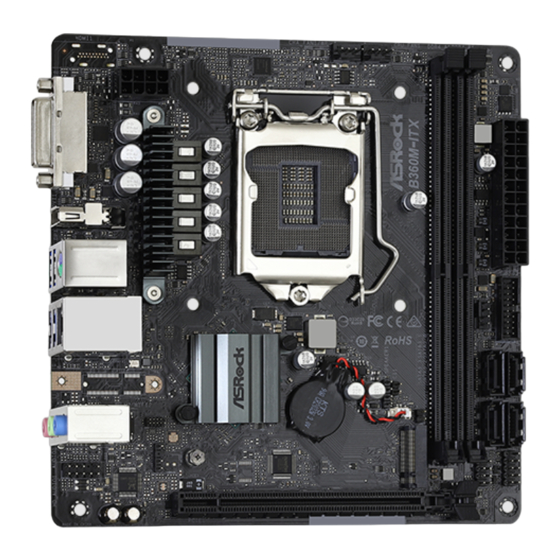
Page 3: Motherboard Layout
B360M-ITX Motherboard Layout CHA_FAN1/WP CPU_FAN1 DISPLAY1 USB 3.2 Gen1 T: USB1 B: USB2 RoHS USB 3.2 Gen2 Top: T: USB1 RJ-45 B: USB2 Intel BAT1 B360 CLRMOS1 BIOS Ultra M.2 PANEL1 USB_3_4 PCIe Gen3 x4 HD_AUDIO1 AUDIO CODEC PCIE1 16 15... - Page 4 No. Description ATX 12V Power Connector (ATX12V1) Chassis Fan / Waterpump Fan Connector (CHA_FAN1/WP) CPU Fan Connector (CPU_FAN1) 2 x 288-pin DDR4 DIMM Slots (DDR4_A1, DDR4_B1) ATX Power Connector (ATXPWR1) USB 3.2 Gen1 Header (USB3_3_4) SATA3 Connector (SATA3_1) SATA3 Connector (SATA3_0) SATA3 Connector (SATA3_3) SATA3 Connector (SATA3_2) System Panel Header (PANEL1)
- Page 5 B360M-ITX I/O Panel No. Description No. Description DVI-I Port (DVI1) LAN RJ-45 Port* DisplayPort 1.2 (DISPLAY1) Microphone (Pink) USB 3.2 Gen1 Ports (USB_1_2) Front Speaker (Lime) PS/2 Mouse/Keyboard Port Line In (Light Blue) USB 3.2 Gen2 Type-A Ports (USB3_1_2) * There are two LEDs on each LAN port. Please refer to the table below for the LAN port LED indications.
-
Page 6: Chapter 1 Introduction
If you require technical support related to this mother- board, please visit our website for specific information about the model you are using. You may find the latest VGA cards and CPU support list on ASRock’s website as well. ASRock website http://www.asrock.com. -
Page 7: Specifications
B360M-ITX 1.2 Specifications Platform • Mini-ITX Form Factor • Solid Capacitor design • Supports 9 and 8 Gen Intel® Core Processors (Socket 1151) • Supports CPU up to 95W • Digi Power design • 5 Power Phase design • Supports Intel® Turbo Boost 2.0 Technology Chipset • Intel®... - Page 8 • HWAEncode/Decode: AVC/H.264, HEVC/H.265 8-bit, HEVC/H.265 10-bit, VP8, VP9 8-bit, VP9 10-bit (Decode only), MPEG2, MJPEG, VC-1 • Dual graphics output: Support DVI-I and DisplayPort 1.2 by independent display controllers • Supports DisplayPort 1.2 with max. resolution up to 4K x 2K (4096x2304) @ 60Hz • Supports DVI-I with max.
- Page 9 (32 Gb/s)** ** Supports Intel® Optane Technology ** Supports NVMe SSD as boot disks ** Supports ASRock U.2 Kit Connector • 1 x Chassis Intrusion Headers • 1 x CPU Fan Connector (4-pin) * The CPU Fan Connector supports the CPU fan of maximum 1A (12W) fan power.
- Page 10 • ErP/EuP ready (ErP/EuP ready power supply is required) * For detailed product information, please visit our website: http://www.asrock.com Please realize that there is a certain risk involved with overclocking, including adjusting the setting in the BIOS, applying Untied Overclocking Technology, or using third-party overclocking tools.
-
Page 11: Chapter 2 Installation
B360M-ITX Chapter 2 Installation This is a Mini-ITX form factor motherboard. Before you install the motherboard, study the configuration of your chassis to ensure that the motherboard fits into it. Pre-installation Precautions Take note of the following precautions before you install motherboard components or change any motherboard settings. -
Page 12: Installing The Cpu
2.1 Installing the CPU 1. Before you insert the 1151-Pin CPU into the socket, please check if the PnP cap is on the socket, if the CPU surface is unclean, or if there are any bent pins in the socket. Do not force to insert the CPU into the socket if above situation is found. - Page 13 B360M-ITX...
- Page 14 Please save and replace the cover if the processor is removed. The cover must be placed if you wish to return the motherboard for after service.
-
Page 15: Installing The Cpu Fan And Heatsink
B360M-ITX 2.2 Installing the CPU Fan and Heatsink... -
Page 16: Installing Memory Modules (Dimm)
2.3 Installing Memory Modules (DIMM) This motherboard provides two 288-pin DDR4 (Double Data Rate 4) DIMM slots, and supports Dual Channel Memory Technology. 1. For dual channel configuration, you always need to install identical (the same brand, speed, size and chip-type) DDR4 DIMM pairs. 2. - Page 17 B360M-ITX...
-
Page 18: Expansion Slot (Pci Express Slot)
2.4 Expansion Slot (PCI Express Slot) There is 1 PCI Express slot on the motherboard. Before installing an expansion card, please make sure that the power supply is switched off or the power cord is unplugged. Please read the documentation of the expansion card and make necessary hardware settings for the card before you start the installation. -
Page 19: Jumpers Setup
B360M-ITX 2.5 Jumpers Setup The illustration shows how jumpers are setup. When the jumper cap is placed on the pins, the jumper is “Short”. If no jumper cap is placed on the pins, the jumper is “Open”. Clear CMOS Jumper... -
Page 20: Onboard Headers And Connectors
2.6 Onboard Headers and Connectors Onboard headers and connectors are NOT jumpers. Do NOT place jumper caps over these headers and connectors. Placing jumper caps over the headers and connectors will cause permanent damage to the motherboard. System Panel Header Connect the power (9-pin PANEL1) switch, reset switch and... - Page 21 B360M-ITX Serial ATA3 Connectors These four SATA3 (SATA3_0: connectors support SATA see p.1, No. 8) data cables for internal (SATA3_1: storage devices with up to see p.1, No. 7) 6.0 Gb/s data transfer rate. (SATA3_2: *If M2_1 is occupied by a SATA- see p.1, No.
- Page 22 Front Panel Audio Header This header is for PRESENCE# (9-pin HD_AUDIO1) connecting audio devices MIC_RET OUT_RET (see p.1, No. 17) to the front audio panel. OUT2_L J_SENSE OUT2_R MIC2_R MIC2_L 1. High Definition Audio supports Jack Sensing, but the panel wire on the chassis must sup- port HDA to function correctly.
- Page 23 B360M-ITX CPU Fan Connector This motherboard pro- (4-pin CPU_FAN1) vides a 4-Pin CPU fan FAN_VOLTAGE CPU_FAN_SPEED (see p.1, No. 3) (Quiet Fan) connector. FAN_SPEED_CONTROL If you plan to connect a 3-Pin CPU fan, please connect it to Pin 1-3. ATX Power Connector...
- Page 24 2.7 M.2_SSD (NGFF) Module Installation Guide (M2_1) The M.2, also known as the Next Generation Form Factor (NGFF), is a small size and versatile card edge connector that aims to replace mPCIe and mSATA. The Socket (M2_1) supports M.2 SATA3 6.0 Gb/s module and M.2 PCI Express module up to Gen3 x4 (32 Gb/s). * If M2_1 is occupied by a SATA-type M.2 device, SATA3_0 will be disabled.
- Page 25 B360M-ITX M.2_SSD (NGFF) Module Support List Vendor Interface ADATA SATA3 AXNS381E-128GM-B ADATA SATA3 AXNS381E-256GM-B ADATA SATA3 ASU800NS38-256GT-C ADATA SATA3 ASU800NS38-512GT-C ADATA PCIe3 x4 ASX7000NP-128GT-C ADATA PCIe3 x4 ASX8000NP-256GM-C ADATA PCIe3 x4 ASX7000NP-256GT-C ADATA PCIe3 x4 ASX8000NP-512GM-C ADATA PCIe3 x4 ASX7000NP-512GT-C...
- Page 26 WDS512G1X0C-00ENX0 (NVME) SATA3 WDS100T1B0B-00AS40 SATA3 WDS240G1G0B-00RC30 V-Color SATA3 VSM100-240G-2280 V-Color SATA3 VLM100-240G-2280B-RD SATA3 WDS100T1B0B-00AS40 SATA3 WDS240G1G0B-00RC30 PCIe3 x4 WDS256G1X0C-00ENX0 (NVME) PCIe3 x4 WDS512G1X0C-00ENX0 (NVME) For the latest updates of M.2_SSD (NFGG) module support list, please visit our website for details: http://www.asrock.com...
- Page 27 感谢您购买华擎 B360M-ITX 主板,这是按照华擎一贯严格质量控制标准生产的 性能可靠的主板。它提供符合华擎质量和耐久性承诺的精良设计和卓越性能。 由于主板规格和 BIOS 软件可能已更新,因此,本文档的内容可能会随时更改,恕不 另行通知。如果本文档有任何修改,则更新的版本将发布在华擎网站上,我们不会另 外进行通知。如果您需要与此主板相关的技术支持,请访问我们的网站以具体了解所 用型号的信息。您也可以在华擎网站上找到最新 VGA 卡和 CPU 支持列表。华擎网站 http://www.asrock.com。 1.1 包装清单 • 华擎 B360M-ITX 主板(Mini-ITX 规格尺寸) • 华擎 B360M-ITX 快速安装指南 • 华擎 B360M-ITX 支持光盘 • 2 x 串行 ATA (SATA) 数据线(选购) • 1 x I/O 面板...
- Page 28 1.2 规格 • Mini-ITX 规格尺寸 平台 • 稳固的电容器设计 • 支持第 8 代和第 9 代 Intel® Core 处理器(插座 1151) • 支持高達 95W 的 CPU • Digi Power design • 5 电源相设计 • 支持 Intel® Turbo Boost 2.0 技术 • Intel® B360 芯片集...
- Page 29 B360M-ITX • 双图形输出 : 通过独立显示控制器支持 DVI-I 和 DisplayPort • 支持 DisplayPort 1.2,60Hz 时最大分辨率达 4K x 2K (4096x2304) • 支持 DVI-I,60Hz 时最大分辨率达 1920x1200 • 通过 DVI-I 和 DisplayPort 1.2 端口支持 HDCP 2.2 • 通过 DisplayPort 1.2 端口支持支持 4K 超高清 (UHD) 播放...
- Page 30 • 风扇转速计 : CPU、机箱、机箱 / 水泵风扇 • 静音风扇(根据 CPU 温度自动调整机箱风扇速度): CPU、 机箱、机箱 / 水泵风扇 • 风扇多种速度控制 : CPU、机箱、机箱 / 水泵风扇 • CASE OPEN(机箱打开)检测 • 电压监控: +12V、+5V、+3.3V、CPU Vcore Microsoft® Windows® 10 64-bit 操作系统 • FCC、CE 认证 • ErP/EuP 支持(需要支持 ErP/EuP 的电源) * 有关详细产品信息,请访问我们的网站: http://www.asrock.com...
- Page 31 B360M-ITX 须认识到超频会有一定风险,包括调整 BIOS 设置,应用“自由超频技术”,或使用 第三方超频工具。超频可能会影响到系统的稳定性,甚至对系统的组件和设备造成损 坏。执行这项工作您应自担风险和自己承担费用。我们对由于超频而造成的损坏概不 负责。...
- Page 32 1.3 跳线设置 此图显示如何设置跳线。将跳线帽装到这些针脚上时,跳线 “短接”。如果这 些针脚上没有装跳线帽,跳线 “开路”。 清除 CMOS 跳线 (CLRMOS1) (见第 1 页,第 14 个) 2 针跳线 CLRMOS1 允许您清除 CMOS 中的数据。要清除和重置系统参数到默认设 置,请关闭计算机,从电源上拔下电源线插头。等候 15 秒后,使用跳线帽将 CLRMOS1 上的针脚短接 5 秒。但是,请勿在更新 BIOS 后立即清除 CMOS。 如果您需要在刚完成 BIOS 更新后清除 CMOS,则必须先启动系统,并在关闭 后再执行清除 CMOS 操作。请注意,密码、日期、时间和用户默认配置文件 只在卸下 CMOS 电池后才会被清除。请记住在清除 CMOS 后取下跳线帽。 如果您清除...
- Page 33 B360M-ITX 1.4 板载接脚和接口 板载接脚和接口不是跳线。不要将跳线帽装到这些接脚和接口上。将跳线帽装到这些 接脚和接口上将会对主板造成永久性损坏。 系统面板接脚 按照下面的针脚分配, (9 针 PANEL1) RESET# 将机箱上的电源开关、 PWRBTN# (见第 1 页, 第 11 个) 重置开关和系统状态指 HDLED- PLED- 示灯连接到此接脚。在 PLED+ HDLED+ 连接线缆前请记下正负 针脚。 PWRBTN(电源开关): 连接到机箱前面板上的电源开关。您可以配置使用电源开关关闭系统的方式。 RESET(重置开关): 连接到机箱前面板上的重置开关。如果计算机死机,无法执行正常重新启动,按重置 开关重新启动计算机。 PLED(系统电源 LED): 连接到机箱前面板上的电源状态指示灯。系统操作操作时,此 LED 亮起。系统处在 S1/S3 睡眠状态时,此 LED 闪烁。系统处在 S4 睡眠状态或关机 (S5) 时,此 LED 熄灭。...
- Page 34 串行 ATA3 接口 这四个 SATA3 接口支持 最高 6.0 Gb/s 数据传输 (SATA3_0: 见第 1 页, 第 8 个) 速率的内部存储设备的 SATA 数据线。 (SATA3_1: 见第 1 页, 第 7 个) * 如果 M2_1 被 SATA 型 M.2 (SATA3_2: 设备占用,SATA3_0 将被禁 见第 1 页, 第 10 个) 用。...
- Page 35 B360M-ITX 前面板音频接脚 此接脚用于将音频设备 PRESENCE# (9 针 HD_AUDIO1) 连接到前音频面板。 MIC_RET OUT_RET (见第 1 页,第 17 个) OUT2_L J_SENSE OUT2_R MIC2_R MIC2_L 1. 高清音频支持插孔感测,但机箱上的面板连线必须支持 HDA 才能正常工作。请按 照我们的手册和机箱手册的说明安装系统。 2. 如果您使用 AC’97 音频面板,请按照以下步骤将它安装到前面板音频接脚: A. 将 Mic_IN (MIC) 连接到 MIC2_L。 B. 将 Audio_R (RIN) 连接到 OUT2_R,将 Audio_L (LIN) 连接到 OUT2_L。...
- Page 36 CPU 风扇接口 此主板提供 4 针 CPU 风 (4 针 CPU_FAN1) FAN_VOLTAGE 扇(静音风扇)接口。如 CPU_FAN_SPEED (见第 1 页, 第 3 个) FAN_SPEED_CONTROL 果您打算连接 3 针 CPU 风扇,请将它连接到针 脚 1-3。 ATX 电源接口 此主板提供 24 针 ATX 电 (24 针 ATXPWR1) 源接口。 (见第 1 页,第 5 个) ATX 12V 电源接口...
- Page 37 B360M-ITX 电子信息产品污染控制标示 依据中国发布的「电子信息产品污染控制管理办法」及 SJ/T 11364-2006「电子 信息产品污染控制标示要求」,电子信息产品应进行标示,藉以向消费者揭露 产品中含有的有毒有害物质或元素不致发生外泄或突变从而对环境造成污染或 对人身、财产造成严重损害的期限。依上述规定,您可于本产品之印刷电路板 上看见图一之标示。图一中之数字为产品之环保使用期限。由此可知此主板之 环保使用期限为 10 年。 图一 有毒有害物质或元素的名称及含量说明 若您欲了解此产品的有毒有害物质或元素的名称及含量说明,请参照以下表格 及说明。 有害物质或元素 部件名称 铅 (Pb) 镉 (Cd) 汞 (Hg) 六价铬 (Cr(VI)) 多溴联苯 (PBB) 多溴二苯醚 (PBDE) 印刷电路板 及电子组件 外部信号连 接头及线材 O: 表示该有毒有害物质在该部件所有均质材料中的含量均在 SJ/T 11363-2006 标准规定 的限量要求以下。...
-
Page 38: Contact Information
Contact Information If you need to contact ASRock or want to know more about ASRock, you’re welcome to visit ASRock’s website at http://www.asrock.com; or you may contact your dealer for further information. For technical questions, please submit a support request form at https://event.asrock.com/tsd.asp... -
Page 39: Declaration Of Conformity
DECLARATION OF CONFORMITY Per FCC Part 2 Section 2.1077(a) Responsible Party Name: ASRock Incorporation Address: 13848 Magnolia Ave, Chino, CA91710 Phone/Fax No: +1-909-590-8308/+1-909-590-1026 hereby declares that the product Product Name : Motherboard B360M-ITX Model Number : Conforms to the following speci cations:... -
Page 40: Eu Declaration Of Conformity
EU Declaration of Conformity For the following equipment: Motherboard (Product Name) B360M-ITX / ASRock (Model Designation / Trade Name) ASRock Incorporation (Manufacturer Name) 2F., No.37, Sec. 2, Jhongyang S. Rd., Beitou District, Taipei City 112, Taiwan (R.O.C.) (Manufacturer Address) EMC —Directive 2014/30/EU (from April 20th, 2016)
Need help?
Do you have a question about the B360M-ITX and is the answer not in the manual?
Questions and answers