Advertisement
Quick Links
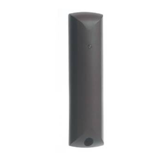
738r
Radio Spyder-
Shock Sensor
1. Activity LED
4. Transmitter module
2. Cover screw
5. Battery
3. Aerial
Fig. 1
1. Activity/Learn LED
5. Battery
2. VR1. Sensitivity potentiometer
6. Back tamper switch
3. Lid tamper switch
7. Mode jumpers
4. Calibration LED
Fig. 2
Fig. 3
Introduction
The 738r Radio Spyder is a vibration and shock sensor capable of
transmitting alarm information using Cooper Security's 868MHz nar-
row band technology. The 738r can report to any compatible Cooper
Security receiver. The receivers can learn the unique identity of each
738r through either an infra-red LED or radio transmissions.
The sensing element within the 738r uses proprietary vibration sensor
technology from Elmdene International.
The installer can adjust the sensitivity of the unit from Low to High and
disable the indicator LED to hide the sensor's activity.
Technical Specification
Part No.
738rEUR-00 (white), 738rEUR-04 (brown)
Zones
Single zone (alarm and tamper channels)
Radio range
Up to 1000m in free space, depending
upon conditions and receiving equipment.
Power Supply
3V CR2 Li/MnO2 battery
Battery Life
Two years
Temperature Range
-10 to +55 °C
Tamper
Front and rear
Dimensions
118 x 30 x 27 (H x W x D)
Weight
46 gms (with battery fitted)
Compliance
EN50131-1 Security Grade 2
EN50130-5 Environmental class II
Figure 1 shows the external appearance and internal layout of the
738r. Figure 2 shows the indicators and controls on the 738r's printed
circuit board.
Compatible Equipment
762r
Two channel receiver
768r/769r
Eight channel receiver
790rEUR-00
Signal Strength Meter
9955/9960
Radio Frequency Expanders
Homelink 75
Domestic Radio Control Unit
Installation
Siting
To ensure the radio transmitter works correctly, do NOT mount the
unit:
Near the floor.
Close to or on large metal structures.
Closer than one meter to mains wiring, or metal water (or gas)
pipes.
Inside metal enclosures.
Next to electronic equipment, particularly computers,
photocopiers or other radio equipment.
Upside down.
Figures 3 and 4 show further considerations when using the 738r as a
shock sensor to monitor, for example, windows.
Do NOT mount the unit on moving panels.
When monitoring large windows with several sections make sure that
738rs are no more than 10m apart in order to ensure full coverage.
Preparing for Installation
1.
Open the case by removing the cover screw and pivoting the
cover up from the bottom.
2.
Remove the PCB by sliding the PCB up out of the PCB brackets.
3.
Install one 3V CR2 Li/MnO2 battery (supplied) in the battery
holder on the PCB.
Learning
1.
Make sure the receiver is in learn mode (see the Installation and
Programming Guide for the receiver) before starting.
2.
Make sure both back and lid tamper switches are closed.
3.
Trigger either the lid or back tamper.
For receivers that use infrared learn hold the transmitter's activity
LED no more than 50mm away from the infra-red learn sensor on
the receiver.
Physical Installation
Mount the back
1.
Hold the back in the chosen location.
2.
Mark two holes through the fixing slots in the back.
3.
Secure the back to the surface using the screws provided.
4.
Make sure the back is flush against the surface and pushes the
tamper bar in far enough to activate the back tamper switch.
5.
Re-fit the PCB into the back of the case.
Fig. 4
Note: Range shown for guidance only.
Sensitivity may vary on different surfaces.
Fig. 5
Fig. 6
Fig. 7
Fig. 8
© Cooper Security Limited 2005
Every effort has been made to ensure that the contents of this
leaflet are correct . However, neither the authors nor Cooper
Security Limited accept any liability for loss or damage caused
or alleged to be caused directly or indirectly by this leaflet. The
contents of this leaflet are subject to change without notice.
Printed and published in the U.K.
Product Support (UK) Tel: +44 (0)870 757 5400
Available between:
08:15 and 17:00 Monday to Friday,
Product Support Fax: (01594) 545401
Part No: 497095 Issue 3
Commissioning
The 738r has several different operating modes. To select the required
mode you must place the jumpers as follows:
Jumper
Function
A
Sensitivity Range Selection
Jumper A selects the high or low sensitivity range. Fit the
jumper to select the low sensitivity range. Remove the
jumper to select the high sensitivity range. The on-board
potentiometer VR1 allows you to adjust the sensitivity
within each range.
B
Sustain Mode
When removed, jumper B selects Sustain mode. This
mode improves the ability of the 738r to discriminate
between alarm events and non-alarm shocks (for example
bird strikes or heavy background noise from busy roads or
nearby railways).
C
Calibration Mode
Fit jumper C in order to adjust the sensitivity or confirm
correct operation. Remove jumper C to put the 738r
into normal operation. Note that the 738r can only enter
calibration mode when the lid tamper switch is open. (See
"To Commission the 738r" below.)
D
Discrete
Fit jumper D to disable the Activity LED. Remove jumper D
to enable the Activity LED.
Note: When delivered from the factory the jumpers are fitted as
follows: A: Removed (high sensitivity), B: Fitted (no sustain), C: Re-
moved (normal operation), D: Removed (Activity LED enabled).
Example Jumper Settings
Reduced Sensitivity (see Fig 5). Use on: hardwood or metal window
and door frames, or on masonry walls.
Normal (see Fig 6). Use on: softwood or plastic window and door
frames, where there is excess paint, a long distance from glass, or
around large glass windows. Note that this is the default setting when
the 738r is delivered from the factory.
Improved Discrimination (see Fig 7). Use in installations with high
background noise, for example near to busy roads or railway lines. If
the shock sensor is not triggered then remove jumper A to select High
Sensitivity. Re-calibrate.
Note: In the above examples, if the shock sensor is not triggered turn
pot VR1 clockwise to make more sensitive and re-calibrate.
To commission the 738r:
1.
Fit jumper C and A to put the 738r into calibration mode at low
sensitivity (see Fig 8).
Note: If the battery is low then the Calibration LED flashes continu-
ously. Fit a new battery.
2.
Turn VR1 fully anti-clockwise. The 738r is now at its lowest sensi-
tivity.
3.
Strike the extremities of the area you wish the 738r to guard. Use
a blunt, hard-surfaced tool, for example a screw driver handle.
The calibration LED flashes when the sensor detects the shock:
once for a small shock, twice for an alarm level shock, and three
times for a very large shock.
4.
Adjust the sensitivity until the calibration LED flashes twice for
each blow on the extremity of the area you wish to guard.
5.
Remove the sensitivity link (jumper A) if the sensor is unable to
detect shocks from the whole of the area you wish to guard.
6.
Remove the calibration link (jumper C) once you have achieved
the desired sensitivity. This places the 738r in its normal operating
mode.
Maintenance
Change the battery every 24 months, or when the control unit indi-
cates low detector battery.
The 738r indicates low battery by sending a message to the receiver.
In addition, the Activity LED will not operate if the battery is low (even
if jumper D is removed).
Cooper Security recommend that you regularly check the calibration
of the 738r, see Commissioning.
Battery Care
DO NOT: Short circuit or attempt to recharge..
Dispose of used batteries in accordance with the current local regula-
tions. DO NOT incinerate, crush, or puncture.
Advertisement

Related Manuals for Cooper Scantronic 738r


Summary of Contents for Cooper Scantronic 738r
- Page 1 The 738r Radio Spyder is a vibration and shock sensor capable of mode you must place the jumpers as follows: transmitting alarm information using Cooper Security’s 868MHz nar- row band technology. The 738r can report to any compatible Cooper Jumper Function...
Need help?
Do you have a question about the Scantronic 738r and is the answer not in the manual?
Questions and answers