Table of Contents
Advertisement
Quick Links
Advertisement
Table of Contents

Subscribe to Our Youtube Channel
Related Manuals for Cooper 7514


Summary of Contents for Cooper 7514
- Page 1 7514 Photo PIR Installation and Programming Guide...
-
Page 2: Table Of Contents
7514r Contents Introduction ................1 Overview.................. 1 External Layout ..................2 Internal Layout..................3 Jumpers ....................3 Technical Specification ............... 4 Specification ................4 General ....................4 Coverage....................4 Radio ....................... 5 Power Supply .................... 5 Electromagnetic Compatibility..............5 Electrical Safety..................5 Compliance Statements ................ -
Page 3: Introduction
7514r Introduction Overview The 7514r Photo PIR is a digital camera linked to a Passive Infra Red (PIR) detector. The field of view of the camera covers the sensitive area of the PIR. When the PIR detects movement it sends a radio signal to a 7510r control unit. -
Page 4: External Layout
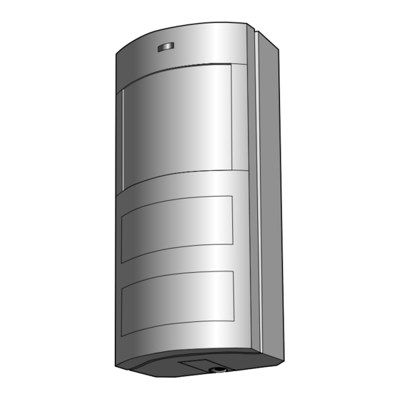
Introduction 7514r External Layout Figure 1 shows the main features of the Photo PIR. To gain access to the interior of the unit undo the screw at the bottom of the case (Figure 2). 1. Activity LED 4. Flash. 2. PIR section. 5. -
Page 5: Internal Layout
7514r Introduction Internal Layout Figure 3 shows the main features inside the body of the Photo PIR. 1. Transceiver. 4. Jumpers. 2. Camera/Flash Batteries 5. Fixing screw knock out. (3 x Lithium 3V CR2). 3. PIR Batteries (2 x AA Alkaline). 6. -
Page 6: Technical Specification
Introduction 7514r Technical Specification Specification General Product name Photo PIR. Manufacturer Cooper Security Ltd. Security Grade Grade 2. Environmental Class II. Dimensions 70mm W, 153mm H, 60mm D. Weight 0.285 kg (with batteries). Case material ABS. Coverage Solid lines = PIR sensitive lobes. Dashed lines = Camera field of view. -
Page 7: Radio
7514r Introduction Radio Radio Section Operating frequency 868.6625MHz, 869.650MHz, 869.6625MHz, 869.675MHz, 869.6875MHz Narrowband. EN 300 220-3. EN 300 330-2 Telefication Transmitter range The range of the transmitter depends on the environment it is installed in. As a guideline, the transmitter will work up to 200m range in free space conditions. -
Page 8: Installation
Flat screwdriver (small), Philips screwdriver, drill with 4mm drill bits, 4mm screws, wall plugs, filler. Site Survey Batteries Cooper Security Ltd supply the unit from the factory with batteries fitted. Insulating plastic tabs prevent the batteries supplying power. To activate the unit remove both plastic tabs. -
Page 9: Site Survey
7514r Installation Site Survey Notes: 1. For the duration of the installation, remove the jumper from pins J2. This defeats the sleep timer. (To avoid losing the jumper fit it to one pin only.) 2. Remember to re-fit the jumper to pins J2 after you have completed physical installation and testing. -
Page 10: Fitting A Wall Tamper
Installation 7514r 1. Open the case and set the main body, including PIR and camera, to one side away from any contamination by dust. 2. Drill out fixing holes from the back of the case as needed (see Figure 3). 3. -
Page 11: Fitting A Corner Wall Tamper
7514r Installation 4. Mount the case back so that the head of the screw protrudes through the cut out and engages the tamper switch when the body of the detector is fitted (see Figure 6). Figure 6. Position of Back Tamper Screw You may have to adjust the height of the screw until it operates the tamper switch. -
Page 12: Completing The Physical Installation
Installation 7514r 2. Cut out the large circle indicated in the back of the Photo PIR case. Make sure that you remove enough material so that the stud of the Wall Tamper Bracket can pass freely through the back of the case. 3. -
Page 13: Programming
7514r Installation Programming Before programming the 7510r control unit please make sure that: a) You understand basic IP (Internet Protocol) terminology. b) You have obtained the necessary information from your Internet Service Provider and ARC . c) You have fitted a GPRS or Ethernet module. At the end of this booklet there is a table that you can use to record the information you need for programming an installation. -
Page 14: Set Up Control Unit's Own Ip Address
Installation 7514r Set Up Control Unit’s Own IP Address When delivered from the factory, the control unit contains no IP address; it can, however, obtain its own IP address from a DHCP server. (To use DHCP leave the control unit’s IP Address blank.) To set up the control unit’s own IP address manually select Installer Mode - IP Network. -
Page 15: Set Up The Ip Address Of The Arc
7514r Installation GPRS APN (Access Point Name) Key in the text of the access point name. GPRS Username Key in your GPRS user name. GPRS Password Key in your GPRS password. Set Up the IP Address of the ARC ARCs can use two types of receiver for alarm messages over IP: an IRIS polling engine, or a specialised application running on a PC. -
Page 16: Setting Up An Email Address
Installation 7514r This option also allows you to key in a unique identifying name for the ARC. Setting Up an Email Address If you wish to send the photos to an email address select Reporting - Email. The control unit offers you the following options: Photos Select Enabled to ensure that the control unit will send the photos by email. -
Page 17: Enabling The Photo Pir
7514r Installation IP Address 1 Key in the IP Address used by Downloader. IP Port 1 Key in the port number that Downloader “listens” to on the remote PC at IP address 1. IP Address 2 Key in an alternate IP Address used by Downloader. IP Port 2 Key in the port number used by the alternate IP address. -
Page 18: Testing
When the lockout timer expires the unit signals the panel the next time it detects movement. Cooper Security Ltd set the lockout timer to three minutes when the Photo PIR leaves the factory. If you wish to change the lockout timer to one minute then remove the jumper link J2 on the back of the PCB (see Figure 3). -
Page 19: Checking Photo Coverage
7514r Testing detection pattern. The unit should alarm within three out of the four walk tests. 3. Stand outside the protected pattern and operate any potential cause of false alarm, e.g., operate lights, open doors, etc. If the unit detects the deliberate cause of false alarm, try readjusting the detector pattern. -
Page 20: Ethernet Connection
Testing 7514r 4. Plug the small end of the USB cable into the USB socket at the back of the control unit. Plug the large end of the USB cable into a USB socket on the PC. 5. On the control unit, enter Installer Mode - Downloading - Connection Type and select Local. -
Page 21: Dealing With Radio Interference
7514r Testing 6. Use the up or down keys to highlight the zone you want to test and then press TEST. 7. Trigger the Photo PIR you want to test. The Photo PIR takes pictures of the area it covers, and sends them to the control unit. -
Page 22: Programming Information Required
7514r Programming Information Required The table below provides a space for you to record the information you need to program the 7510r. : GPRS Module fitted? No (skip to next User name section) Password 7510r’s own Address Using DHCP? IP Address (skip to (not Subnet mask... - Page 23 7514r NOTES Page 21...
- Page 24 Every effort has been made to ensure that the contents of this book are correct. However, neither the authors nor Cooper Security Limited accept any liability for loss or damage caused or alleged to be caused directly or indirectly by this book.
Need help?
Do you have a question about the 7514 and is the answer not in the manual?
Questions and answers