Table of Contents
Advertisement
Quick Links
Vibro-I 10 – 80 m² Series 2
Manual
Please be sure to read this entire user manual prior to use of the equipment.
Please read all safety instructions carefully.
This user manual is part of the product. Keep it in a safe place for future reference.
Replacement manuals can be downloaded from our Webpage at:
www.sanimembranes.com
Version: 20221219
Advertisement
Table of Contents

Related Manuals for SANI Membranes Vibro-I 2 Series

Summary of Contents for SANI Membranes Vibro-I 2 Series
- Page 1 Vibro-I 10 – 80 m² Series 2 Manual Please be sure to read this entire user manual prior to use of the equipment. Please read all safety instructions carefully. This user manual is part of the product. Keep it in a safe place for future reference. Replacement manuals can be downloaded from our Webpage at: www.sanimembranes.com Version: 20221219...
-
Page 2: Table Of Contents
1. Contents Description..............................4 Introduction ............................4 Validity ..............................6 Symbols ..............................7 System ............................... 8 Parts list ..............................8 System description ..........................8 Safety ............................... 13 Intended use ............................13 Personnel qualification ........................14 Media ..............................14 Pressurized components ........................15 Leaking fluids ............................ - Page 3 Clean water flux ........................... 26 Storage of membranes ........................27 Assembly and disassembly of the Vibro-I unit ..................28 Installation and assembly of new Vibro-I units ................... 28 Disassembly of the Vibro-I cartridge ....................28 Re-assembly of the Vibro-I cartridge ....................30 Storage of used HP1 membrane modules ...................
-
Page 4: Description
2. Description Please be sure to read this entire user manual prior to use of the equipment. Please read all safety instructions carefully. This user manual is part of the product. Keep it in a safe place for future reference. A. - Page 5 allows for filtration with no need for pre- The Vibro-I range is a modular design filtration even for high solids loading and based on the 2.5 m² Free Flow Plate™ high viscosity media. The Free Flow Plate™ module HP1. A Vibro-I unit consists of one element has an integrated and open or more assembled HP1 modules mounted permeate channel design.
-
Page 6: Validity
B. Validity This manual applies to Vibro-I units in the following versions: Vibro-I 10 – 80 m² Series 2 • Designed for vertical installation of 1 or 4 cartridges each containing 4 or 8 HP1 modules resulting in installed membrane areas of 10 m², 20 m², 40 m² and 80 m² Please refer to separate manuals covering Vibro-I 7.5 –... -
Page 7: Symbols
C. Symbols As warning of danger, all text statements in these instructions to be noted will be marked as follows: WARNING This symbol denotes a possible danger with medium risk that death or (severe) injury may result if it is not avoided. CAUTION This symbol denotes a possible danger with a low risk that moderate or minor injury may result if it is not avoided. -
Page 8: System
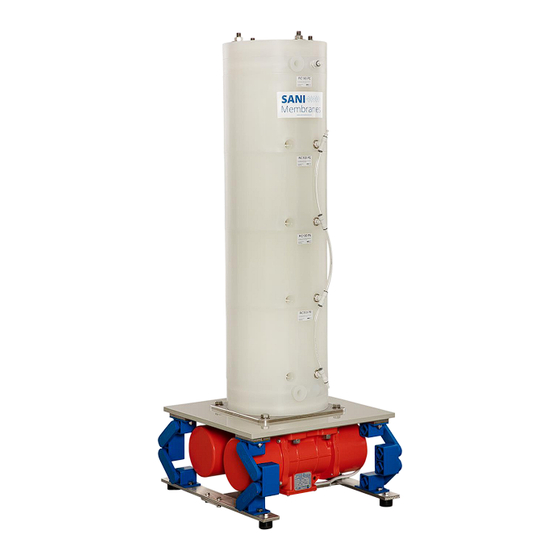
3. System A. Parts list 1. Vibro-I drive frame 2. Vibro-I cartridge 3. Permeate manifold system 4. Liquid manifolds for the 40 or 80 m² units B. System description The Vibro-I system is a modular design based on the 2.5 m² HP1 membrane module. A cartridge assembly (2) consisting of 4 or 8 HP1 modules is mounted on the Vibro-I drive frame (1). - Page 9 Vibro-I drive frame The Vibro-I drive frame generates the vibrations for the Vibro-I unit. It constists of 5. Industrial springs, 4 off 6. Vibro-I motor, 2 off 7. Base plate 8. Vibro-I stand Vibro-I drive frame The two Vibro-I motors (6) together with the four industrial springs (5) create the vibrations for the unit.
- Page 10 The Vibro-I cushion assembly (11) consists of 15. Vibro-I cushion 16. Media inlet/outlet part 17. Top/bottom part 18. Media inlet/outlet ports Vibro-I Cushion Assembly Bottom inlet assembly shown The Vibro-I cushion (15) is secured between a media inlet/outlet part (16) and a top/bottom part (17).
- Page 11 Liquid manifolds Each HP1 module has two permeate ports. In the standard configurations one is blinded, and the other is configured with a push-fit T-connection. As an alternative option the permeate port can be configured with a Mini-TC clamp connection. The standard configuration includes a permeate manifold joining the push-fit T-connections of the HP1 modules with 10 mm tubing.
- Page 12 On the 20 m² cartridges the permeate manifold is divided into an upper and a lower manifold. These are joined to a 12 mm drain line via a Y-piece, or joined in a stainless steel manifold with push-fit fittings when used for the 40 and 80 m² units. The 40 and 80 m²...
-
Page 13: Safety
The Vibro-I is intended to filter media and can only be used with HP1 membrane modules from SANI Membranes. The Vibro-I can only be used together with a feed system with a built-in safety to protect the Vibro-I against over-pressure. -
Page 14: Personnel Qualification
This instruction manual is part of the Vibro-I. The Vibro-I is intended exclusively for use in accordance with this instruction manual. The Vibro-I must only be used for intended use. The following are examples of improper use WARNING: Unauthorized modifications and technical changes to the Vibro-I are improper use. •... -
Page 15: Pressurized Components
The operator should always seek the applicable safety information for the media to be filtered as well as media used for the cleaning and storage of membrane modules (e.g. handling and storage and conduct in emergency situations). WARNING Personal safety equipment should always be worn when applicable (e.g. safety goggles, safety gloves etc.). -
Page 16: Leaking Fluids
E. Leaking fluids If the fluid system is leaking, liquid spill can cause a serious health danger depending on media. The operator should always seek the applicable safety information for the media to be filtered (e.g. handling and storage and conduct in emergency situations). Personal safety equipment should always be worn when applicable (e.g. -
Page 17: Accessories And Spare Parts
• Device failure ATTENTION • Only use accessories, consumables and spare parts that are in technically perfect condition. The use of accessories, consumables and spare parts not approved by SANI Membranes is the sole responsibility of the operator. Version: 20221219... -
Page 18: Operation
5. Operation A. Introduction The standard way to run the assembled unit is to pump feed in through a media port in the bottom of the Vibro-I membrane assembly. The permeate is collected via the permeate outlets using a permeate manifold and the retentate is leaving the unit at the desired rate through a media port in the top. -
Page 19: Permeate System
B. Permeate system The manifold is designed to avoid negative transmembrane pressure (TMP) as this can cause Avoid pressure damage to the membrane modules. A negative TMP can drop using larger occur when reducing the feed pressure dramatically or diameter stopping the feed system quickly. -
Page 20: Feed And Retentate System
C. Feed and retentate system All Vibro-I systems need a supply of liquid from a feed system. There are endless ways of designing a feed system all depending on the application and scale, and the degree of automation required. When designing a feed system, the maximum allowed feed pressure of the HP1 membrane modules must be taken into consideration. -
Page 21: Preparation For First Use
D. Preparation for first use Conditioning of new membrane Before using a new membrane with product it should be prepared for use. New membranes are provided with a protective layer of water-soluble glycerin and / or preservative solutions that should be removed before first use. This is done by flushing the membrane for 30 minutes with clean hot water (50-55 °C). - Page 22 Maintain a minimum retentate flow out of each cartridge to avoid dead-end type • filtration. A suitable retentate flow is normally 800 – 1200 L/h per cartridge (so that means 3.2 – 4.8 m³/h for a 40 or 80 m² plant). This is application dependent and if the media is highly concentrated or very viscous the flow rates may need to be higher.
-
Page 23: Examples Of Membrane Filtration Process Configurations
F. Examples of membrane filtration process configurations Membrane filtration batch mode with concentration in tank Simple configuration for viscosities up to • ”cream level” The trans membrane pressure is regulated • with the regulation valve The retentate flow is regulated with the •... - Page 24 Continuous membrane filtration mode with mix pump – high solids or high viscosity Configuration for achieving high • Vent Regulation viscosity or high concentration valve The retentate is circulating using • Retentate tank a mix flow pump in order to ensure sufficient mixing of the Permeate tank...
-
Page 25: Cip Operation
Multi-stage systems often incorporate 5-8 stages in order to optimize the performance of the membrane. Below is shown a simplified diagram of a three-stage system with mix-flow at the third stage. The optimal process configuration is highly application dependent, and an application specific process configuration must be thought trough to each industrial application including CIP system, degree of automation, temperature control system etc. -
Page 26: Clean Water Flux
A typical CIP routine for processes with organic material could consist of: 1. Drain for product 2. Flush the system with 55 °C water 3. Caustic wash, 55 °C at pH 11-11.5 for 20-25 min 4. Flush with water for 5 min 5. -
Page 27: Storage Of Membranes
I. Storage of membranes The membrane should never be allowed to dry out. Keep the system filled with water between batches. For longer periods it is recommended to add a suitable solution to keep the membranes wetted, and to prevent bacterial growth during storage. The storage solution should be selected in accordance with the chemical compatibility of the specific membrane material. -
Page 28: Assembly And Disassembly Of The Vibro-I Unit
6. Assembly and disassembly of the Vibro-I unit A. Installation and assembly of new Vibro-I units The Vibro-I unit consists of a motor assembly and one or four cartridge assemblies. The motor assembly should be installed in the facility floor or on a support frame. A machine specific foundation layout is available upon request. - Page 29 diagonally placed rods. 20 m² cartridges should always be bolted onto a stable support to minimize the risk of accidents during disassembly. Due to the lower height the 10 m² cartridges can – with caution – be disassembled without being bolted onto a support. Overview of the cartridge components: 1.
-
Page 30: Re-Assembly Of The Vibro-I Cartridge
C. Re-assembly of the Vibro-I cartridge For this instruction for re-assembly of the cartridge, please refer to the overview of components in the previous section. 1. Make sure that all parts are intact and clean 2. Place the bottom Vibro-I cushion assembly (2) in the desired orientation by sliding it over the 4 rods (5). - Page 31 7. For the 20 m² cartridge the rods (5) are joined by a bolt after the first 4 HP1 modules. Mount the joining bolt and the upper rod before placing the last 4 HP1 modules 8. Place the top Vibro-I cushion assembly (2) on the upper HP1 module. For correct aligninment a mark has been applied to the plastic near the inlet port.
-
Page 32: Storage Of Used Hp1 Membrane Modules
11. Fittings for the permeate connections are mounted on the permeate outlets. It is important to secure the permeate outlets from turning inside the module using an Allen wrench on the opposite side of the module. When tightening use Mount the an Allen key permeate opposite to keep the... -
Page 33: Service And Maintenance
7. Service and maintenance A. Tightening and re-tightening the Vibro-I top bolts The 4 nuts (8) on top of each module tower must be tightened with a torque wrench adjusted to 35 Nm for the 7.5 m², 38 Nm for the 10m², 40 Nm for the 15 m² and 42 Nm for the 20 m² (The nuts must be re-tightened after 8 hours in operation of the Vibro-I after each re- assembly). -
Page 34: Exchanging Or Re-Inflating The Vibro-I Cushion
C. Exchanging or re-inflating the Vibro-I cushion 1. Disassemble the Vibro-I cushion assembly by un-screwing the 8 M8 Allen bolts 2. Clean the top/bottom part and the inlet part of the Vibro-I cushion assembly with 50% ethanol 3. Place the top/bottom part of the Vibro-I cushion assembly on a flat surface 4. - Page 35 If there is no visual differences it may be required to analyze samples from each permeate line to locate the problem: 1. If more Vibro-I units operate in parallel evaluate the permeate from each unit in order to identify the unit in question 2.
-
Page 36: Flux Performance
Note: The squeeze-off solution can potentially lead to local back-pressure conditions in the isolated HP1 membrane module, and this can lead to further membrane defects in that module. Permanent solution: The affected HP1 membrane module is replaced with a new module. Stop the production clean the Vibro-I and drain it. -
Page 37: Maintenance And Exchange Of The Wheels
F. Maintenance and exchange of the wheels If the Vibro-I model is on wheels, these are wear parts that will need to be replaced. Regular inspection of the wheels is recommended. The frequency of such inspection depends on the use of the machine. The estimated lifetime of the wheels is around 1000 hours of operation but the actual lifetime will dependent on conditions such as the floor surface finish for instance. -
Page 38: Technical Data
PES, PVDF, hydrophilic PTFE The HP1 can be equipped with your membrane of choice. SANI Membranes have a line of standard MF and UF membranes from Synder, Microdyn-Nadir and others on stock. Most commercially available membranes can however also be used with the HP1. Please, do not hesitate to contact us with your membrane wishes. -
Page 39: Conformity
9. Conformity The Vibro-I system is CE marked to demonstrate compliance with relevant regulations including the European Machine, Electrical and Pressure Directives. The Vibro-I can conform to GMP/FDA/EC regulations for materials in contact with food and other sanitary standards on request. Version: 20221219...
Need help?
Do you have a question about the Vibro-I 2 Series and is the answer not in the manual?
Questions and answers