
Related Manuals for E-T-A 921

Summary of Contents for E-T-A 921
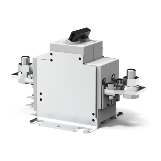
- Page 1 921/922/437 Batterie-Schutzschalter/-Trenner Battery Isolation/Main Switches E N G I N E E R I N G T E C H N O L O G Y...
- Page 2 Schäden am Gerät und am Fahrzeug führen. the equipment itself and to the installation. E-T-A übernimmt gegenüber Kunden oder Dritten E-T-A is unable to accept responsibility for customer keine Haftung, Gewährleistung oder Garantie für Män- or third party liability, warranty claims or damage gel oder Schäden, die durch fehlerhaften Einbau oder...
- Page 3 Fernausschaltung. battery isolation switch. B. TYPEN 921/922 B. SERIES 921/922 Die ein- und zweipoligen Trenner (921, 922) sind Leis- Single and double pole Battery Isolation Switches tungstrenner mit elektrischer Fern-ausschaltung ohne series 921, 922 are fitted with a remote electrical Überlastauslöser nach VDE 0660/EN 60947.
-
Page 4: Technische Daten
Ambient temperature: Typ 437 -40 °C … 60 °C series 437 -40 °C … +60 °C Typen 921, 922 -40 °C … 75 °C -40 °F … +140 °F Schutzart (IEC 60529): series 921, 922 -40 °C … +75 °C Betätigungsbereich... -
Page 5: Montage
Montage Installation EINBAULAGE: MOUNTING ATTITUDE: • Bei mechanischer Ferneinschaltung über Bowden- • unimportant with remote disconnection only. zug beliebig. Hinweis: Note: Bei mechanischer Ferneinschaltung (Bestellbezeich- If manual reconnection is specified (ordering refer- nung: -BC) über Bowden-zug (nur ohne -B Kunststoff- ence: -BC) a flexible cable will be needed (only without gehäuse) ist vom Kunden eine Rückzugvorrichtung moulded enclosure -B). - Page 6 2 Schutzschalter wie im Kap. 5 anschließen. Wenn 2 Make all electrical connections in accordance with Spritzwasserschutz erforderlich ist, nur dafür paragraph 5, ensuring the use of geeignete Kabeldurch-führungen verwenden. suitable cable glands if water protection is required. 3 Den gegebenfalls vorhandenen Betätig-ungsgriff 3 Turn the operating knob on the housing to “OFF”, if auf dem Kunststoffgehäuse auf „OFF“...
-
Page 7: Elektrischer Anschluss
2 Connect the main battery cable to terminal I of the anschließen (Fig. 6). switch unit. 3 Connect the remote control circuitry and auxiliary 3 Steuerleitung und Hilfskontakte gemäß Fig. 7 (921/922) oder Fig. 8 (437) anschließen. contacts as shown in fig.7 (921/922) or fig. 8 (437). - Page 8 11 - 12: Öffner/break/Si1 13 - 14: Schließer/make/Si2 a - b: FA-Spule /FA-coil 23 - 24: Schließer/make/Si2 FA: Fernausschaltspule/remote disconnection coil FE: Ferneinschaltspule/ remote reconnection coil 7.a 921: U 7. b 922: U Main Main +2 -2 FE 3 11 13...
- Page 9 3 Die Fernauslösespule „FA“ ist nur für Im-puls- 3 The remote disconnect coil “FA” is impulse rated betrieb geeignet. Es wird empfohlen, die Spule only. It is recommended that this is connected to über die „tote“ Seite (II oder -2) (Fig. 7.a + 7.b) des the “dead”...
- Page 10 Fig. 9 AUSLÖSUNG DISCONNECTION Series 921 (single pole) and 922 (double pole) can be Die Typen 921 (einpolig) und 922 (zweipolig) werden manuell oder durch einen Impuls auf die Fernauslöse- disconnected manually or by an impulse to the remote spule ausgelöst.
- Page 11 WIEDEREINSCHALTUNG RECONNECTION Die Wiedereinschaltung ist möglich durch: Reconnection is by means of: • Fernbedienung mit Bowdenzug (Fig. 10) • flexible cable provided by the user (fig. 10) • mechanisch mit einem Drehknopf (Fig. 12) • the manual operating knob (fig. 12) •...
- Page 12 E-T-A Elektrotechnische Apparate GmbH Industriestraße 2-8 90518 Altdorf Phone +49 9187 10-0 Fax +49 9187 10-397 Email: info@e-t-a.de global.e-t-a.com...
Need help?
Do you have a question about the 921 and is the answer not in the manual?
Questions and answers