Advertisement
Quick Links
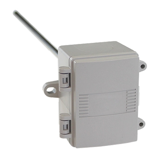
NetX™ NT-DRS
Duct Remote Sensor
INSTALLATION MANUAL
WWW.NETWORKTHERMOSTAT.COM
TABLE OF CONTENTS
BEFORE YOU START
WHAT IS IN THE BOX?
REMOTE SENSOR CALLOUT
MOUNTING LOCATIONS
LED STATUS
ONE (1) YEAR LIMITED WARRANTY
SPECIFICATIONS
TYPICAL WIRING DIAGRAM
Page 1
BEFORE YOU START
Please read the entire install manual. The NT-DRS will need to be
correctly wired and configured for proper operation.
INTRODUCTION
The Network Thermostat NT-DRS duct remote sensor is designed
to sense air temperature at locations remote to the X7 or X5
series thermostats. Up to three (3) NT-DRS sensors can be used
on the X7 or X5 series thermostats in addition to multiple NT-URS
sensors configured for separate functions.
WHAT IS IN THE BOX?
● (1) NT-DRS Universal Remote Sensor
● (1) Installation Manual
REMOTE SENSOR CALLOUT
1
Number of Sensors Jumper
2
Wiring to Thermostat
3
Wiring to external probe
4
Remote Sensor Configuration DIP Switches
5
Diagnostic LED
1
1
1
1
3
3
3
4
MOUNTING LOCATIONS
Due to the weatherproof enclosure, the NT-DRS can be mounted
in an interior or exterior location.
INSTALL STEPS
B TIP: If you are replacing an existing sensor, take a picture of
the wiring for reference.
1. Install the X7 or X5 series thermostat according to the
instruction manual supplied with it.
Install cable (Red Arrow) from the thermostat to the remote
sensor location. Maximum distance is 300ft. (90m).
Use CAT5 or CAT5e unshielded, or 1-Pair Twisted Shielded
Cable with Drain and nominal capacitance of 12 pF/ft or less.
Use riser or plenum jacket as required by local code.
C CAUTION: Disconnect power to the thermostat or remove
thermostat faceplate before connecting either end of the
cable.
1
2. Once a suitable spot is
selected, drill a 9.5 - 12 mm
(3/8" - 1/2") hole for the probe.
Then Mount the NT-DRS. A
foam gasket on the back of the
enclosure provides a tight seal
2
against any air leaks.
3
4
5
3. The enclosure has a hinged cover
with a latch. Open the cover by
pulling slightly on the latch on the
right side of the enclosure. At the
same time pulling on the cover.
240322-01
Advertisement

Related Manuals for Network Thermostat NetX NT-DRS


Summary of Contents for Network Thermostat NetX NT-DRS
- Page 1 INTRODUCTION instruction manual supplied with it. NetX™ NT-DRS The Network Thermostat NT-DRS duct remote sensor is designed Install cable (Red Arrow) from the thermostat to the remote to sense air temperature at locations remote to the X7 or X5 Duct Remote Sensor sensor location.
- Page 2 4. Run the sensor cable from the thermostat to the sensor 8. Set the DIP Switches on 10.Reattach the thermostat faceplate to the backplate. (See your location. A 1/2" NPT threaded connection hole is provided in the bottom right of the thermostat installation manual for instructions.) the bottom of the enclosure.
- Page 3 LED STATUS ONE (1) YEAR LIMITED WARRANTY The NT-DRS includes a Diagnostic LED that can help you Network Thermostat™ warrants to the original purchaser that troubleshoot your installation and sensor operation. this product will be free from defects in workmanship and...
- Page 4 TYPICAL WIRING DIAGRAM To Thermostat RS2 RS+V RS1 General NetX RSBus Wiring Instructions ● Only 1 Sensor for each type per thermostat except for INDOOR Sensor ● All non indoor sensors and 1 INDOOR sensor wired to RS1-to-RS1, RS2-to-RS2 and RS+V-to-RS+V NT-URS ●...
Need help?
Do you have a question about the NetX NT-DRS and is the answer not in the manual?
Questions and answers