Table of Contents
Advertisement
Quick Links
PNEUMERCATOR
Liquid Level Control Systems
Date: 2015.09.30 21:12:49 -04'00'
email=peter@pneumercator.com, c=US
DN: cn=Peter Sinkiwskij, o=Pneumercator Co., Inc., ou=Headquarters,
Digitally signed by Peter Sinkiwskij
Peter Sinkiwskij
MAINTENANCE MANUAL
© COPYRIGHT 2015 PNEUMERCATOR CO., INC.
TMS1000N Operations and Maintenance Manual.docx
OPERATION &
MODEL TMS1000N
1785 EXPRESSWAY DRIVE NORTH
HAUPPAUGE, NY 11788
TEL: (631) 293-8450
FAX: (631) 293-8533
http://www.pneumercator.com
SINGLE
NON-HAZARDOUS
TANK
MONITORING
SYSTEM
September 30, 2015
Advertisement
Table of Contents

Related Manuals for Pneumercator TMS1000N


Summary of Contents for Pneumercator TMS1000N
- Page 1 SINGLE Liquid Level Control Systems NON-HAZARDOUS TANK MONITORING Peter Sinkiwskij Digitally signed by Peter Sinkiwskij DN: cn=Peter Sinkiwskij, o=Pneumercator Co., Inc., ou=Headquarters, email=peter@pneumercator.com, c=US Date: 2015.09.30 21:12:49 -04'00' SYSTEM OPERATION & MAINTENANCE MANUAL MODEL TMS1000N © COPYRIGHT 2015 PNEUMERCATOR CO., INC.
-
Page 3: Table Of Contents
OPERATION & MAINTENANCE MANUAL TMS1000N Note: A separate INSTALLATION MANUAL is available, but NOT required for TMS1000N operation. TABLE OF CONTENTS Page Section 1 FRONT PANEL DESCRIPTION Overview ........................4 Display ........................5 Audible Annunciator ....................5 Section 2 OPERATION Power-up Sequence .................... -
Page 4: Front Panel Description
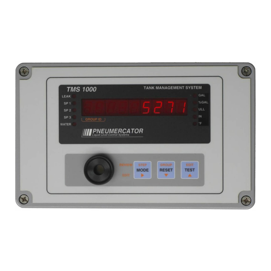
SECTION 1 – FRONT PANEL DESCRIPTION 1.1 OVERVIEW As illustrated in Figure 1-1 below, the TMS1000N front panel consists of an LED data display with visual alarm and mode annunciators, audible alarm annunciator, and user -friendly pushbutton controls. Figure 1-1 – Front Panel Overview TMS1000N Operations and Maintenance Manual.docx... -
Page 5: Display
1-2 below. Figure 1-2 – Front Panel Display 1.3 AUDIBLE ANNUNCIATOR The audible annunciator integrated into the Front Panel activates for any programmed alarm condition alerting site personnel to this fact. TMS1000N Operations and Maintenance Manual.docx September 30, 2015 PAGE 5... -
Page 6: Power-Up Sequence
Display shows “systEn/init” (System/Initialization). 4. Firmware version identification. The TMS displays the current firmware versions installed in the system. This information may be requested by Pneumercator’s Technical Support department for troubleshooting purposes. 5. Visual display and audible alarm check. Display shows "888888888" (88888888) with all LEDs on, audible alarm beeps twice. -
Page 7: Overview
Test: The Test mode allows visual verification of display operation, audible verification of the audible annunciator, and self-verification of critical system hardware. TMS1000N Operations and Maintenance Manual.docx September 30, 2015 PAGE 7... -
Page 8: View Mode
The visual annunciator will remain active until the alarm or error condition is eliminated. If subsequent alarm errors, or warnings occur, the audible annunciator will again be activated. TMS1000N Operations and Maintenance Manual.docx September 30, 2015... - Page 9 Ullage = 1380 Gallons Product Level = 106.8 Inches Water Level = 1.5 Inches Temperature = 72.1°F Product Name = Water Pressing the MODE button until the BEEP, will select each item TMS1000N Operations and Maintenance Manual.docx September 30, 2015 PAGE 9...
-
Page 10: Access Mode
ID. If the user enters the INVENTORY LOG menu, which stores up to 6 records, depressing GROUP will step to the next inventory record and the GROUP ID display field will represent the inventory record number 1 through 6. TMS1000N Operations and Maintenance Manual.docx September 30, 2015 PAGE 10... -
Page 11: Test Mode
The TEST mode is initiated by depressing the TEST pushbutton. This action activates all of the front panel display LED segments and LED annunciators for visual verification, and will produce a double beep from the audible annunciator for audible verification. TMS1000N Operations and Maintenance Manual.docx September 30, 2015 PAGE 11... -
Page 12: Access Mode Menus
INVENTORY will increment the system to the next menu. i.e. DELIVERY, then SALES, etc. The (RESET) button at the flashing term such as INVENTORY will decrement the system to the next menu. i.e. RETURN, then EVENTS, etc. TMS1000N Operations and Maintenance Manual.docx September 30, 2015 PAGE 12... -
Page 13: Inventory Log
LOG submenu showing INVENTORY. *Holding the STEP (MODE) button until one TMS beep at RETURN advances the TMS to the top of the INVENTORY menu showing mm-dd TMS1000N Operations and Maintenance Manual.docx September 30, 2015 PAGE 13... -
Page 14: Delivery
LOG submenu showing DELIVERY. *Holding the STEP (MODE) button until one TMS beep at RETURN advances the TMS to the top of the DELIVERY menu showing mm-dd TMS1000N Operations and Maintenance Manual.docx September 30, 2015 PAGE 14... -
Page 15: Sales
LOG submenu showing SALES. *Holding the STEP (MODE) button until one TMS beep at RETURN advances the TMS to the top of the SALES menu showing mm-dd TMS1000N Operations and Maintenance Manual.docx September 30, 2015 PAGE 15... -
Page 16: Thefts
LOG submenu showing THEFTS. *Holding the STEP (MODE) button until one TMS beep at RETURN advances the TMS to the top of the THEFTS menu showing mm-dd TMS1000N Operations and Maintenance Manual.docx September 30, 2015 PAGE 16... -
Page 17: Product Order
LOG submenu showing ORDERS. *Holding the STEP (MODE) button until one TMS beep at RETURN advances the TMS to the top of the ORDERS menu showing mm-dd TMS1000N Operations and Maintenance Manual.docx September 30, 2015 PAGE 17... -
Page 18: Water Removal
Water cycle again. Water *Pressing the Mode/Step button at the Return decrements the TMS back out to the top of the Water TMS main menu. mm-dd TMS1000N Operations and Maintenance Manual.docx September 30, 2015 PAGE 18... -
Page 19: Alarms
*Holding the STEP (MODE) button until one TMS beep at RETURN advances the TMS to the top of the ALARMS menu showing mm-dd For description of Alarms, Warnings, or Errors, see Appendix A. TMS1000N Operations and Maintenance Manual.docx September 30, 2015 PAGE 19... -
Page 20: Events
*Holding the STEP (MODE) button until one TMS beep at RETURN advances the TMS to the top of the EVENTS menu showing mm-dd For description of Alarms, Warnings, or Errors, see Appendix A. TMS1000N Operations and Maintenance Manual.docx September 30, 2015 PAGE 20... -
Page 21: Configuration
HEADER will increment the system to the next menu. i.e. TANK, then PROBE, etc. The (RESET) button at the flashing term such as HEADER will decrement the system to the next menu. i.e. RETURN, then DIAL OUT, etc. TMS1000N Operations and Maintenance Manual.docx September 30, 2015 PAGE 21... -
Page 22: Header
Entry Type: select list Range Limits: N/A Default/Initialized value: gr VoL gr VoL = Gross Volume LEVEL = Units of measure Item List: PctVoL = Percent Gross Volume nEtVoL = Net Volume TMS1000N Operations and Maintenance Manual.docx September 30, 2015 PAGE 22... - Page 23 1-9 minutes. Although the horn is silenced, the LED for that condition will continue to be visually illuminated until alarm condition is satisfied. This feature can be disabled by selecting NONE. Entry Type: select list Range Limits: (None, 1-9) Default/Initialized value: none TMS1000N Operations and Maintenance Manual.docx September 30, 2015 PAGE 23...
- Page 24 *Pressing the EDIT (TEST) button at RETURN decrements the TMS back to the CONFIG submenu showing HEADER. *Holding the STEP (MODE) button until one TMS beep at RETURN advances the TMS to the top of the HEADER menu showing ACCESS CODE. TMS1000N Operations and Maintenance Manual.docx September 30, 2015 PAGE 24...
-
Page 25: Tank
Mogas = Mogas EtHaNL = Ethanol EtH 10 = 10% Ethanol EtH 15 = 15% Ethanol EtH 20 = 20% Ethanol EtH 85 = 85% Ethanol User = User-defined Tank Name TMS1000N Operations and Maintenance Manual.docx September 30, 2015 PAGE 25... - Page 26 LEDs. It can always be used to control an integrated relay. Entry Type: 3 digit numeric, % Range Limits: 0-99.9% Default/Initialized value: 90. 0 TMS1000N Operations and Maintenance Manual.docx September 30, 2015 PAGE 26...
- Page 27 Horn – Critical Low Volume Set Point: Enables the audible annunciator for the Critical CritLHorn Low Set Point if associated with one of the numbered set point LEDs. Entry Type: select list Range Limits: (Yes, No) Default/Initialized value: no TMS1000N Operations and Maintenance Manual.docx September 30, 2015 PAGE 27...
- Page 28 Horn – Low Low Temperature Set Point: Enables the audible annunciator for the Low Low LLtp Horn Temperature Set Point. Entry Type: select list Range Limits: (Yes, No) Default/Initialized value: yes TMS1000N Operations and Maintenance Manual.docx September 30, 2015 PAGE 28...
- Page 29 Tank Radius: This entry requires the user to enter the tank radius. The radius is half of the diameter. Needed for tank types of FLAT, CUSTOM 3, and CONE. Entry Type: 4 digit numeric Range Limits: 0- 999.9 Default/Initialized value: 0. 0 TMS1000N Operations and Maintenance Manual.docx September 30, 2015 PAGE 29...
- Page 30 Tank Height: This entry requires the user to enter inside tank height. Needed for tank type of VERTICAL, CUSTOM 8, and CONE. Entry Type: 5-digit numeric Range Limits: 0 - 1999.9 Default/Initialized value: 0. 0 TMS1000N Operations and Maintenance Manual.docx September 30, 2015 PAGE 30...
- Page 31 *Pressing the EDIT (TEST) button at RETURN decrements the TMS back to the CONFIG submenu showing TANK. *Holding the STEP (MODE) button until one TMS beep at RETURN advances the TMS to the top of the TANK menu showing TANK ENABLE. TMS1000N Operations and Maintenance Manual.docx September 30, 2015 PAGE 31...
-
Page 32: Probe
This can only be performed if the float is buoyant in the product. Entry Type: 4-digit numeric Range Limits: +/- 0.0 - 299.9 Default/Initialized value: -000. 0 TMS1000N Operations and Maintenance Manual.docx September 30, 2015 PAGE 32... - Page 33 *Pressing the EDIT (TEST) button at RETURN decrements the TMS back to the CONFIG submenu showing PROBE. *Holding the STEP (MODE) button until one TMS beep at RETURN advances the TMS to the top of the PROBE menu showing PROBE TYPE. TMS1000N Operations and Maintenance Manual.docx September 30, 2015 PAGE 33...
-
Page 34: Relay Tank
Relay Trigger – Low Low Product: List of relays to be triggered by the Low Low Product LoLo trig Set Point Entry Type: numeric list Range Limits: (01-04).(01-04).(01-04) Default/Initialized value: no. n o. n o TMS1000N Operations and Maintenance Manual.docx September 30, 2015 PAGE 34... - Page 35 RELAY TANK. *Holding the STEP (MODE) button until one TMS beep at RETURN advances the TMS to the top of the RELAY TANK menu showing CRITICAL HIGH TRIGGER. TMS1000N Operations and Maintenance Manual.docx September 30, 2015 PAGE 35...
-
Page 36: Relay Contact Closure
RELAY CC. *Holding the STEP (MODE) button until one TMS beep at RETURN advances the TMS to the top of the RELAY CC menu showing CONTACT CLOSURE TRIGGER. TMS1000N Operations and Maintenance Manual.docx September 30, 2015 PAGE 36... -
Page 37: Relay Sensor
*Pressing the EDIT (TEST) button at RETURN decrements the TMS back to the CONFIG submenu showing RELAY SENSOR. *Holding the STEP (MODE) button until one TMS beep at RETURN advances the TMS to the top of the RELAY SENSOR menu showing SENSOR TRIGGER. TMS1000N Operations and Maintenance Manual.docx September 30, 2015 PAGE 37... -
Page 38: Relay Site
*Pressing the EDIT (TEST) button at RETURN decrements the TMS back to the CONFIG submenu showing RELAY SITE. *Holding the STEP (MODE) button until one TMS beep at RETURN advances the TMS to the top of the RELAY SITE menu showing THEFT. TMS1000N Operations and Maintenance Manual.docx September 30, 2015 PAGE 38... -
Page 39: Relay Mode
Point and deactivate on a High Set Point. This would allow the tank to be filled before deactivating the pump. Note: Pumps are NOT controlled directly by the TMS. The TMS would simply provide a signal to represent when the pump should run. TMS1000N Operations and Maintenance Manual.docx September 30, 2015 PAGE 39... - Page 40 Default/Initialized value: Inp no Inp no = Feature disabled (no tank selected) Item List: Inp 1 = Latch Off for sensor 1 activity Inp 2 = Latch Off for sensor 2 activity TMS1000N Operations and Maintenance Manual.docx September 30, 2015 PAGE 40...
- Page 41 *Pressing the EDIT (TEST) button at RETURN decrements the TMS back to the CONFIG submenu showing RELAY MODE. *Holding the STEP (MODE) button until one TMS beep at RETURN advances the TMS to the top of the RELAY MODE menu showing NORMALLY. TMS1000N Operations and Maintenance Manual.docx September 30, 2015 PAGE 41...
-
Page 42: Contact Closure Input
L1faiL Line 1 Fail L2pass Line 2 Pass L2faiL Line 2 Fail L3pass Line 3 Pass L3faiL Line 3 Fail L4pass Line 4 Pass L4faiL Line 4 Fail Pump Pump TMS1000N Operations and Maintenance Manual.docx September 30, 2015 PAGE 42... - Page 43 *Pressing the EDIT (TEST) button at RETURN decrements the TMS back to the CONFIG submenu showing CC INPUT. *Holding the STEP (MODE) button until one TMS beep at RETURN advances the TMS to the top of the CC INPUT menu showing CC ENABLE. TMS1000N Operations and Maintenance Manual.docx September 30, 2015 PAGE 43...
-
Page 44: Sensor Input
WELL Well genrtr Generator Water Water OiL Oil Vault Vault Hi res High Reservoir Lo RES Low Reservoir High High HiHigh High-High Lo Low LoLo Low-Low trbine Turbine Dispan Dispenser Pan TMS1000N Operations and Maintenance Manual.docx September 30, 2015 PAGE 44... - Page 45 Fault Enable: In supervised mode the system will detect and report short-circuited and open-circuited sensor field wiring when used in conjunction with fault reporting sensors. Fault-reporting leak sensors will require the Pneumercator type "FL" series or compatible. Select YES to enable the fault detection.
-
Page 46: Inventory
Tuesday: The TMS will record an inventory snapshot in the Inventory Log on Tuesday at each different time programmed above.. Entry Type: select list Range Limits: (Yes, No) Default/Initialized value: no TMS1000N Operations and Maintenance Manual.docx September 30, 2015 PAGE 46... - Page 47 *Pressing the EDIT (TEST) button at RETURN decrements the TMS back to the CONFIG submenu showing INVENTORY. *Holding the STEP (MODE) button until one TMS beep at RETURN advances the TMS to the top of the INVENTORY menu showing HOUR 1. TMS1000N Operations and Maintenance Manual.docx September 30, 2015 PAGE 47...
-
Page 48: Theft
Saturday Close: User enters the hour of the day in 24-hour format for Saturday that the facility CLOSES for business and the tanks are not available. Entry Type: 4-digit numeric hours, minutes Range Limits: 00’00 – 23’59 Default/Initialized value: 00`00 TMS1000N Operations and Maintenance Manual.docx September 30, 2015 PAGE 48... - Page 49 *Pressing the EDIT (TEST) button at RETURN decrements the TMS back to the CONFIG submenu showing THEFT. *Holding the STEP (MODE) button until one TMS beep at RETURN advances the TMS to the top of the THEFT menu showing M-F OPEN. TMS1000N Operations and Maintenance Manual.docx September 30, 2015 PAGE 49...
-
Page 50: Modem
*Pressing the EDIT (TEST) button at RETURN decrements the TMS back to the CONFIG submenu showing MODEM. *Holding the STEP (MODE) button until one TMS beep at RETURN advances the TMS to the top of the MODEM menu showing MODEM. TMS1000N Operations and Maintenance Manual.docx September 30, 2015 PAGE 50... -
Page 51: Dialout
Item List: data Data: A computer running TMSComm or any other data device that uses a communications protocol provided by Pneumercator to communicate to the TMS. --- Not available tty TTY: A Teletype style data dump to any device capable of receiving this text only broadcast. - Page 52 Default/Initialized value: no System Error – Dial-Out: Defines if the TMS initiates a dial-out for any System Err diaL Error/Event. Entry Type: Select List above Range Limits: (Yes, No) Default/Initialized value: no TMS1000N Operations and Maintenance Manual.docx September 30, 2015 PAGE 52...
- Page 53 *Pressing the EDIT (TEST) button at RETURN decrements the TMS back to the CONFIG submenu showing DIAL OUT. *Holding the STEP (MODE) button until one TMS beep at RETURN advances the TMS to the top of the DIAL OUT menu showing TEL LOCAL. TMS1000N Operations and Maintenance Manual.docx September 30, 2015 PAGE 53...
-
Page 54: Clock
*Pressing the EDIT (TEST) button at RETURN decrements the TMS back to the ACCESS submenu showing CLOCK. *Holding the STEP (MODE) button until one TMS beep at RETURN advances the TMS to the top of the CLOCK menu showing MM-DD-YY. TMS1000N Operations and Maintenance Manual.docx September 30, 2015 PAGE 54... -
Page 55: Initialize Data
*Pressing the EDIT (TEST) button at RETURN decrements the TMS back to the ACCESS submenu showing INIT DATA. *Holding the STEP (MODE) button until one TMS beep at RETURN advances the TMS to the top of the INIT DATA menu showing INIT DATA. TMS1000N Operations and Maintenance Manual.docx September 30, 2015 PAGE 55... -
Page 56: Appendix A Detailed Definitions Of Tms Alarm, Events, And Warnings Codes
Discriminating leak sensor is in PRODUCT alarm Sensor Water LEAK SENSOR ALARM - sensor # Sensor Name WATER Note: ISCC or Intrinsically Safe Contact Closure is synonymous with Leak/Pt. Level Sensor TMS1000N Operations and Maintenance Manual.docx September 30, 2015 PAGE 56... - Page 57 SENSOR FAULT - OPEN sensor # sensor name CIRCUIT SENSOR FAULT sensor # sensor name Wiring fault with ES825-200F Note: ISCC or Intrinsically Safe Contact Closure is synonymous with Leak/Pt. Level Sensor TMS1000N Operations and Maintenance Manual.docx September 30, 2015 PAGE 57...
- Page 58 FRONT END COMMUNICATION Indicates a communications failure on the Main Board. Power off the TMS1000N, wait at least two seconds, and power on the TMS1000N. If the Warning persists, the Main Board, P/N 900699-1, will need to be repaired or replaced.
- Page 59 "Low Product" will be displayed. This condition is usually associated with probes requiring "Special Tank TOP mounting". These minimum gauging points are programmed for all enabled tanks in the changed in the Config Tank Menu. TMS1000N Operations and Maintenance Manual.docx September 30, 2015 PAGE 59...
-
Page 60: Appendix B Maintenance
Pneumercator service provider to make the necessary arrangements. The TMS1000N will be able to detect many conditions, including memory failure within the system, probe communication issues, and sensor wiring faults (when equipped with a Pneumercator fault detecting sensor). - Page 61 OPERATION & MAINTENANCE MANUAL TMS1000N Refer to the documentation supplied with the sensor for proper HS100ND testing procedures. Contact Pneumercator for additional information. Press the Test button associated with the remote alarm. It is Remote Alarms: Includes all RA also recommended to simulate an alarm on the controlling and select LC1000 systems system to verify the operation of the remote alarm.
-
Page 62: Appendix Ctms Dip Switch Settings
APPENDIX C TMS Main Board Dip Switch Settings The TMS1000N is equipped with a Main System Board that is supplied with DIP switches that have been factory set. Switches are housed in a small rectangular Red enclosure and are numbered 1-4. - Page 64 TMS Series Pneumercator, here and after referred to as PCO, warrants its TMS Series family of products to be free of defects in material and workmanship for a period of Twelve (12) months from date of installation or Fifteen (15) months from date of invoice, whichever comes first.
Need help?
Do you have a question about the TMS1000N and is the answer not in the manual?
Questions and answers