Table of Contents
Advertisement
Quick Links
Advertisement
Table of Contents

Related Manuals for DRUCK & TEMPERATUR Leitenberger LR-Cal SOLAR


Summary of Contents for DRUCK & TEMPERATUR Leitenberger LR-Cal SOLAR
- Page 1 SOLAR Instructions Manual Instructions Manual Temperature Calibrator LR-Cal SOLAR DRUCK & TEMPERATUR Leitenberger GmbH Bahnhofstr. 33 72138 Kirchentellinsfurt / GERMANY Tel. +49 (0) 7121-90920-0 • Fax +49 (0) 7121-90920-99 E-Mail: DT-Export@Leitenberger.de www.druck-temperatur.de - 1 -...
-
Page 2: Table Of Contents
SOLAR Instructions Manual INSTRUCTIONS MANUAL REV. DATE SOLAR 12.3a 19 Dec 2022 VALID FROM SERIAL NUMBER J810 09 INDEX WARNING ................................... 3 1 - INTRODUCTION ................................4 1.1 - P ........................4 URPOSE AND SUMMARY OF INSTRUCTIONS - SCOPE OF SUPPLY ..............................5 2.1 - N : .................................. -
Page 3: Warning
SOLAR Instructions Manual WARNING Hazardous voltages are present in this electrical equipment during operation. Non-observance of the safety instruction can result in severe personal injury or property damage. Only qualified personnel should work on or around this equipment after becoming familiar with all warnings, safety notices, and maintenance procedures contained herein. -
Page 4: Introduction
SOLAR Instructions Manual 1 - INTRODUCTION 1.1 - Purpose and summary of instructions This manual contains the instructions for the use and maintenance of the following equipment: Portable Temperature Calibration mod.: SOLAR. The instructions reported in this manual, for the above-mentioned equipment, are those relevant to: * Start-up preparation * Operation description * Using of the equipment... -
Page 5: Scope Of Supply
SOLAR Instructions Manual 2 - SCOPE OF SUPPLY 2.1 - Name: Portable Temperature Calibrator SOLAR, including accessories, as listed (reference to paragraph 2.7) 2.2 - Technical data: Environmental range: temperature +10÷+45°C, R.H. max. 80%. • Operative range : 200÷+1100°C **. (1000°C for model at 100V) •... -
Page 6: Service (Function)
SOLAR Instructions Manual 2.3 - Service (function): The portable temperature calibrator Solar has been designed for: • Control & calibration of thermocouples, temperature sensors, in the laboratory and in the field, in conformity with ISO 9000 standard. • Thermal test on materials. The calibrator has been designed to reduce the EMC effect in accordance with the harmonised regulation for residential, commercial, light industry and heavy industry. -
Page 7: General Recommendations
SOLAR Instructions Manual 3 - GENERAL RECOMMENDATIONS ➔ ATTENTION The processor regulator has been configured in factory with the parameters suited to work in the respect of the technical specifications. Don’t change these parameters to avoid malfunction or breaking of the calibrator with risks of serious personal injury. - Page 8 SOLAR Instructions Manual Fig.1 Fig.2 Fig.3 - Advice: • The temperature difference is proportional to the difference between the diameter of the probe and the diameter of the hole. • Do not insert the probe when the instrument has already reached the set temperature; thermal shock causes instability and breakage of the sensitive element.
-
Page 9: Safety Instructions
SOLAR Instructions Manual 4 - SAFETY INSTRUCTIONS ATTENTION • Due to the fact that the thermostat is a portable instrument to be used in the field, it is very important to ensure that the socket has been earthen correctly when connecting it to the power supply. -
Page 10: Preparation Of Operation
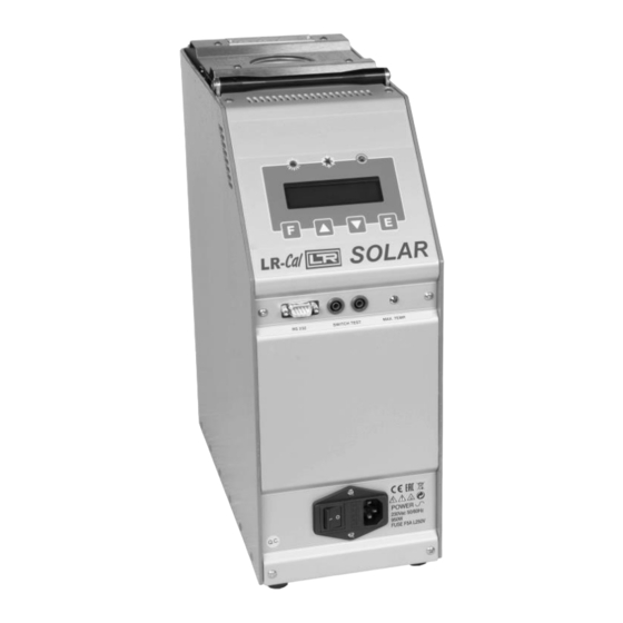
SOLAR Instructions Manual 5 - PREPARATION OF OPERATION • Remove the calibrator from the packaging (5.1.1) and place it on a flat surface (5.1.2). • Make sure that the instrument has been correctly earthen. • Supply the oven with line 230V, 50Hz + earth (5.1.3). •... - Page 11 SOLAR Instructions Manual COMMAND LIST POS. DESCRIPTION SUPPLY SOCKET MAIN SWITCH PROTECTION FUSES SWITCH TEST BUSHES RS-232 SOCKET MAX TEMPERATURE LAMP THERMOREGULATOR +DISPLAY HEATING LED COOLING LED SWITCH TEST LED EXTERNAL PROBES SOCKETS (OPTIONAL) POLARITY SUPPLY INDICATION LAMP - 11 -...
-
Page 12: Operation Procedure
SOLAR Instructions Manual 6 - OPERATION PROCEDURE 6.1 - Operation description The SOLAR calibrator consist of an equaliser block INCONEL made fitted with holes into which the sensors to be calibrated are inserted. A heater element heats the block and an electronic controller with static relay output checks and regulates the temperature. -
Page 13: Ventilation Holes
SOLAR Instructions Manual 6.2.4 - Ventilation holes On the base and at the rear of the calibrator holes have been made so that air may circulate inside the calibrator; do not obstruct these ventilation holes. 6.2.5 - Heating resistance The resistance is made in ceramic fibre with a spiral-heating element. The power of the resistance is 850W and it can reach temperatures approaching 1100°C. -
Page 14: Start-Up Instructions
SOLAR Instructions Manual 6.3 - Start-up instructions ATTENTION: • The calibrator can only be used correctly if the user has a good knowledge of its basics. • Before starting with the calibration following the instructions for the positioning of the equalising block (paragraph 5);... - Page 15 SOLAR Instructions Manual Before any calibration follow the general recommendation: • Starting the calibration only at ambient temperature: thermal shock can break the sensitive element of the probe and cause harm to operator. • To fit the equaliser block inside the oven: reference to paragraph 5.1.4. •...
- Page 16 SOLAR Instructions Manual Cooling To reduce the oven’s temperature, change the set point and wait for the cooling. By request the solar with the standard block may be completed with the cooling device using only with max. temperature of 650°C. How to use: •...
-
Page 17: Use Of The Functions
SOLAR Instructions Manual 6.4 - Use of the functions 6.4.1 - Reading the external probes (only for model –2I) It is possible to display one or two probes tied to the EXT and REF inputs. The following probes can be connected: 1. -
Page 18: Switch Test (Sw. On Sw. Off)
SOLAR Instructions Manual 6.4.2 - Switch test (SW. ON SW. OFF) It is possible to control the intervention point of thermostats by the 'SWITCH TEST' function. • Insert the thermostat’s end in the most suitable hole of the calibrator pit (refer to notes in paragraph 3). -
Page 19: Maintenance Instructions
SOLAR Instructions Manual 7 - MAINTENANCE INSTRUCTIONS 7.1 - Routine inspections instructions • Check that the holes of the calibrator are cleaned, any liquid or oil inside the hole could make oxides or dirty during the use at high temperature. •... -
Page 20: Typical Faults
SOLAR Instructions Manual 9 - TYPICAL FAULTS Before carrying out these operations the instrument must be disconnect from the electricity supply; the equaliser block must be at ambient temperature. N° FAULT DESCRIPTION FAULTY COMPONENT OR METHOD FOR REMOVAL FUNCTION The calibrator does not work - The fuse (3) is cut off. -
Page 21: Appendices
SOLAR Instructions Manual 10 - APPENDICES 10.1- Regulation Front Panel EXTERNAL PROBE INPUT REFERENCE PROBE INPUT Selectable between Pt100, Pt100 Selectable between Pt100, Pt100 3W, Tc K, Tc S, Tc N, Tc J, Tc R 3W, Tc K, Tc S, Tc N, Tc J, Tc R type type according to the probe you according to the probe you calibrate calibrate... - Page 22 SOLAR Instructions Manual DESCRIPTION OF REGULATOR’S MENU The calibrator has three menu levels( see item10.2): at the first level there are the functions for the continuous usage, at the second level there are more specific functions for the regulation of the calibrator, at the third level there are the typical functions for each calibrator and the calibration procedures.
- Page 23 SOLAR Instructions Manual SW. OFF Switch off; it displays the temperature at which the thermostat connected to the terminals "SWITCH TEST" is open. The value is reset each time the power supply fails or by pressing the two ” ”...
- Page 24 SOLAR Instructions Manual This is the key to step the third menu level. Press or key to set the number recorded in the " ACCESS KEY parameters at the third menu level, and press "F" + keys at the same time (it is not necessary to confirm the choice by pressing the E key) to step to the third menu level.
- Page 25 SOLAR Instructions Manual First Calibration point. Press the key to set the value read with the standard thermometer and press E key to accept - 25 -...
- Page 26 SOLAR Instructions Manual Second Calibration point. Press the key to set the value read with the standard thermometer and press E key to accept. CAL: INT (Y/N): This writing can have three different configurations. CAL: INT (Y/N) if Cal_chnl is set on INT CAL: EXT (Y/N) if Cal_chnl is set on EXT CAL: REF (Y/N)
- Page 27 SOLAR Instructions Manual 3. Choose two calibration points depending on the appliance range or the field where one wishes to carry out calibration. (For example 0 and 450°C for PT100, 200 and 800°C for the thermocouples). 4. Connect the signal generator to the EXT input, generating the first calibration value. See the instructions for the connection.
-
Page 28: Microprocessor Regulator: Control Description
SOLAR Instructions Manual 10.2 - Microprocessor regulator: control description - 28 -... -
Page 30: Communication Protocol Rs232/C
SOLAR Instructions Manual 10.3 - Communication Protocol Rs232/C General characteristics: Baud Rate: 9600 Parity: N. Bit: Bit of stop: The communication runs in half duplex way which means that is transmission and reception could not be contemporaneously present. The regulator replies only after receiving command; it never replies itself. The command and reply are ASCII character string, as detailed forward. - Page 31 SOLAR Instructions Manual Each commands string are ASCII character succession. First is $ character; the next must indicate the instrument address (default 1) and than is the command (4 characters). Possibility: RVAR (data reading) WVAR (data writing) The ultimate part of string is depending of a type command. The character (cr) concludes the sequence DATA READING: Example 1) reading of the Set Point (0 variable): the command string is: $1RVAR0_<cr>...
- Page 32 SOLAR Instructions Manual DATA WRITING: FLOAT VARIABLES For writing you use the command WVAR. Examples 1) writing of the Set point to 132,5°C If the unity of measure of the temperature is already °C it is enough to write the SET POINT (see the table of the “VARIABILES”...
-
Page 33: List Of Spare Parts: 230V Model
SOLAR Instructions Manual 10.4 - List of spare parts: 230V model (Numerical references related to the enclosed drawings) POS. DESCRIPTION CODE CUP SOCKET + 6A FILTER 3SCH28366 5A FAST PROTECTION FUSES fuse 5X20 5A VARISTOR - DIAM. 14 3MRC14D391 SWITCH TEST PLUG-IN 3B&BPAN10A RS-232 3ICIDSUB09PS... -
Page 34: Declaration Of Conformity And Check Report
SOLAR Instructions Manual 10.5 - Declaration of conformity and check report The declaration of conformity CE is at the end of the English manual, the test report is included with the calibrator "Declaration of conformity" DRUCK & TEMPERATUR Leitenberger GmbH Bahnhofstr. - Page 35 SOLAR Instructions Manual - 35 -...
- Page 36 SOLAR Instructions Manual DRUCK & TEMPERATUR Leitenberger GmbH Bahnhofstr. 33 72138 Kirchentellinsfurt / GERMANY Tel. +49 (0) 7121-90920-0 • Fax +49 (0) 7121-90920-99 E-Mail: DT-Export@Leitenberger.de www.druck-temperatur.de - 36 -...
Need help?
Do you have a question about the LR-Cal SOLAR and is the answer not in the manual?
Questions and answers