Advertisement
Quick Links
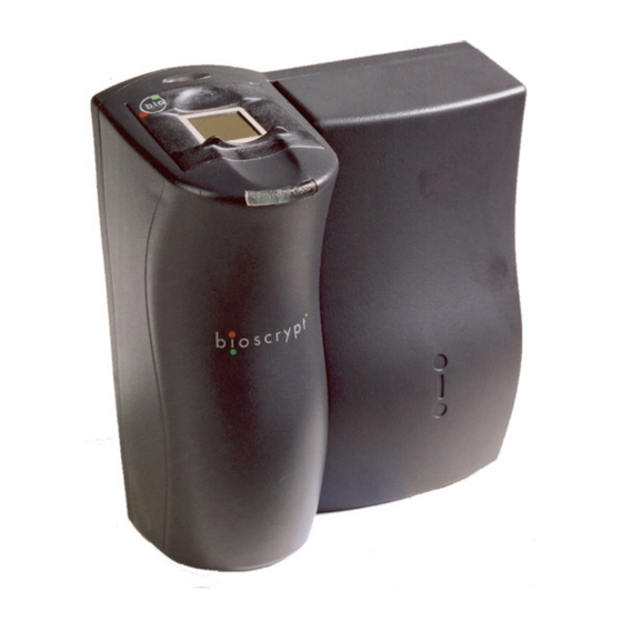
Checklist For Unpacking
Veri-Series reader
(V-Smart and V-Station differ
from picture shown)
Wall mounting plate /
Mullion mounting plate
(V-Smart and V-Station differ
from picture shown )
Pigtail cable
(not included for V-Station)
Documentation
Veri-Series Setup
Guide
Documentation provided with your new fingerprint reader is installed
onto your computer when you install the VeriAdmin software (also
available online at http://www.bioscrypt.com).
documentation you can use Windows Explorer (available from the
Start
Menu
Files\Bioscrypt\VeriAdmin\Docs or another location that you
defined during the installation procedure.
provided in Adobe® Acrobat® format (PDF). The Adobe Acrobat
reader is available on the CD or on-line at www.adobe.com.
© Copyright 2004 Bioscrypt Inc. All rights reserved. Document #430-00111-17
under
Programs)
Veri-Series Setup Guide
to
navigate
The documentation is
Tools
1/8" security hex
key
Hardware
(4) #6-32 screws
(4) #6 self-tapping
screws
(4) #4-8 wall
anchors
(14) crimps
(1) plastic Aux port
door
(2) #4-40 screws
To view the
to
C:\Program
1
Advertisement

Related Manuals for bioscrypt Veri Series


Summary of Contents for bioscrypt Veri Series
- Page 1 Files\Bioscrypt\VeriAdmin\Docs or another location that you defined during the installation procedure. The documentation is provided in Adobe® Acrobat® format (PDF). The Adobe Acrobat reader is available on the CD or on-line at www.adobe.com. © Copyright 2004 Bioscrypt Inc. All rights reserved. Document #430-00111-17...
-
Page 2: Other Required Equipment
2000, or XP 486-compatible 16 MB RAM 30 MB disk space Door controller Networking cable RS-232/RS-485 Converter P/S for converter CD with VeriAdmin User software and Documentation documentation (included on VeriAdmin CD) © Copyright 2004 Bioscrypt Inc. All rights reserved. Document #430-00111-17... - Page 3 Warranty and Returns section of this document. Please see the Release Announcement document on the CD- ROM for the latest updates to this and other documentation. © Copyright 2004 Bioscrypt Inc. All rights reserved. Document #430-00111-17...
- Page 4 Bioscrypt. The “bioscrypt on board™” logo signifies that Bioscrypt's biometric technology has been integrated into this product. It provides the assurance that Bioscrypt's high standards of biometric quality and security reside within the product. © Copyright 2004 Bioscrypt Inc. All rights reserved. Document #430-00111-17...
- Page 5 Green – Pass Red – Fail Conductive Plastic Fingerprint Sensor RidgeLock™ to aid in consistent finger placement Power Indicator MIFARE ® iCLASS™ smart card reader ABS Plastic Body Aux. Port © Copyright 2004 Bioscrypt Inc. All rights reserved. Document #430-00111-17...
- Page 6 Red – Fail Fingerprint Sensor LCD Backlit RidgeLock™ Display Power Indicator Illuminated Keypad Some models: MIFARE ® iCLASS™ smart card reader or HID Proximity reader Aux. Port ABS Plastic Body © Copyright 2004 Bioscrypt Inc. All rights reserved. Document #430-00111-17...
- Page 7 : The V-Flex has all the capabilities and features of the ™ V-Prox described above except that there is no built-in HID proximity card reader. Therefore the V-Flex requires an external Wiegand input signal. The V-Flex is designed for © Copyright 2004 Bioscrypt Inc. All rights reserved. Document #430-00111-17...
- Page 8 Also, this is the first product to offer Ethernet support. It is probably the most versatile product in the Veri-Series. MIFARE is a registered trademark of Philips Semiconductors ® iCLASS™ is a trademark of HID Corporation © Copyright 2004 Bioscrypt Inc. All rights reserved. Document #430-00111-17...
- Page 9 Wiegand output is typically used to send the user information (ID number and facility code from card) to an access control panel, but this connection is not strictly required. © Copyright 2004 Bioscrypt Inc. All rights reserved. Document #430-00111-17...
-
Page 10: Preparing Wiring
Power – should be 18 – 22 AWG (10 – 7 MWG) wire, 2 conductors. Earth Ground – use a single wire with heaviest gauge reasonable. Warning: Do not use Power Ground as a substitute for Earth Ground. © Copyright 2004 Bioscrypt Inc. All rights reserved. Document #430-00111-17... - Page 11 Power GND Black Black Signal GND Green w/ White Black/Red Power input (9-24 VDC) Blue w/ White *(9-12 VDC) for V-Smart Reserved Blue Red/White Earth ground White w/ Black Green/Yellow © Copyright 2004 Bioscrypt Inc. All rights reserved. Document #430-00111-17...
- Page 12 TTL Data 1 Out TTL Ground 4. [RS-485 network only]: Use a daisy chain network design as depicted in the following figure. Do not use a star or other multi-drop configuration. © Copyright 2004 Bioscrypt Inc. All rights reserved. Document #430-00111-17...
- Page 13 6. [RS-485 network only]: RS-485 supports distances up to 4,000 feet (1,200 meters) and/or 31 readers. To extend these limitations, contact Bioscrypt Technical Support. Typically no end-of-line termination is required unless the total run exceeds 2,000 feet. © Copyright 2004 Bioscrypt Inc. All rights reserved. Document #430-00111-17...
- Page 14 (i.e., the Internet). *Ethernet communication is supported in firmware versions 7.10 and higher. VeriAdmin 5.10 or higher is required for administration over Ethernet. © Copyright 2004 Bioscrypt Inc. All rights reserved. Document #430-00111-17...
- Page 15 Connect RJ11 to reader and DB9 to PC COM port. b. Plug pigtail cable into reader (if not a V-Station) and connect power to appropriate conductors identified in the charts on pages 11 and 12. © Copyright 2004 Bioscrypt Inc. All rights reserved. Document #430-00111-17...
- Page 16 Network Setup dialog. This dialog is also reached by clicking on this icon: . Select the serial (COM) port(s) you intend to use or Ethernet and click OK. It is recommended that you check “Auto”. © Copyright 2004 Bioscrypt Inc. All rights reserved. Document #430-00111-17...
- Page 17 First click on the Comm port or Ethernet within the network tree which you have connected the unit to (the icon). Then click on the “Add Unit” button (lower left). © Copyright 2004 Bioscrypt Inc. All rights reserved. Document #430-00111-17...
- Page 18 The network tree shown on the left will show a small icon representing the current unit , just below the icon under the port you selected. Double-click on this icon to open the Unit Parameters dialog. © Copyright 2004 Bioscrypt Inc. All rights reserved. Document #430-00111-17...
- Page 19 Wiegand Tab: Wiegand parameters NOTE: We do not recommend changing the Aux. port Baud rate at this time. 4. Repeat steps 2-4 (skipping 3a) for the next reader until all readers are configured. © Copyright 2004 Bioscrypt Inc. All rights reserved. Document #430-00111-17...
- Page 20 (to further minimize the risk of compromised or lost cards), then this can be done through an RS-485 network or by making the appropriate changes to the reader through the Aux port. © Copyright 2004 Bioscrypt Inc. All rights reserved. Document #430-00111-17...
Need help?
Do you have a question about the Veri Series and is the answer not in the manual?
Questions and answers