
Related Manuals for Gentner AP 10

Summary of Contents for Gentner AP 10
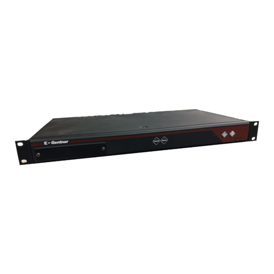
- Page 1 T elephone Interface Installation & Operation Manual Perfect Communication through Technology, Service, and Education.
- Page 2 Gentner Part No. 800-150-201 May 2001 (Rev. 1.1) ©2001 Gentner Communications Corporation. All rights reserved. No part of this manual may be reproduced in any form or by any means without written permission from Gentner Communications Corporation. Printed in the United States of America.
-
Page 3: Table Of Contents
able of Contents Introduction ......1 Congratulations ............1 Product Registration . - Page 4 Operating Your AP10 ..........14 Answering a Call .
-
Page 5: Introduction
• INTRODUCTION Introduction Congratulations Congratulations on purchasing the Audio Perfect™ 10 (AP10) telephone interface. The AP10 uses the latest digital technology to maintain the highest possible quality audio. The AP10 is designed as an accessory to the Audio Perfect 800 (echo cancelling, audio processing, microphone mixing matrix) to add telephone lines into audioconferences. -
Page 6: Product Registration
Product Registration Please register your AP10 online by visiting Gentner Technical Support at www.gentner.com. When your product is properly registered, Gentner Communications is better able to serve you should you require technical assistance. Registration information is also used to notify you of upgrades, new product information, etc. -
Page 7: Features
• UNPACKING INTRODUCTION Unpacking Ensure that the following items (See Figure 1, below) were received with Gentner Communications your shipment: is not responsible for prod- uct damage incurred dur- ing shipment. You must make claims directly with the carrier. Inspect your shipment carefully for obvious signs of damage. -
Page 8: Controls And Connections
• CONTROLS AND CONNECTIONS INTRODUCTION Controls and Connections Figure 2. AP10 front-panel controls Front View The AP10 front-panel controls (see Figure 2, above) perform the following functions: 1. Transmit LED This bicolor LED indicates the audio levels being transmitted from the room to the telephone line. 2. -
Page 9: Touch-Tone Dialing
Gentner unit’s G-LINK IN connector. 3. G-Link Out This RJ-45 connector is part of the G-Link RS-485 LAN that provides serial control and status of the hybrid. The last Gentner unit in the local G-Link network must terminate G-LINK OUT with a G- Link terminator. -
Page 10: Before You Install
• BEFORE YOU INSTALL INTRODUCTION Before You Install Power Requirements The AP10 automatically accommodates voltage requirements of 100–240VAC, 50/60Hz, 30W. Telephone Line Requirements The AP10 model operates on a standard analog telephone line and connects to the telephone system with a standard RJ-11C modular jack. If you do not have an RJ-11C jack where you want to install your AP10, call your telephone company for installation. -
Page 11: Installation
• INSTALL ATION INSTALL ATION & OPERATION Installation & Operation Installation The AP10 is designed for easy installation and setup. All necessary interface connections are made through rear-panel connectors. This makes for easy installation, removal and, if necessary, service. The following block diagram (see Figure 4, below) shows the AP10 when installation is complete in an Audio Perfect system. -
Page 12: Connecting The Unit
In [2] and G-Link Out [3] connectors are designed for setting up +(positive), –(negative), and your G-Link network. G-Link connections between AP units are (ground). connected in daisy-chain fashion using category five twisted-pair cable. AP800 AP 10 G-Link G-Link Terminator AP 10 Audio: Transmit and Receive G-Link G-Link Figure 8. -
Page 13: Assigning Device Id Numbers
• INSTALL ATION INSTALL ATION & OPERATION 2. The first Gentner unit in the chain must have the G-Link In connector If the Gentner units to be [2] terminated with a G-Link terminator (provided). networked are stacked ver- tically, connect them using 3. -
Page 14: Dip Switch Settings
• CONFIGURATION INSTALL ATION & OPERATION DIP Switch Settings The AP10 has a variety of operational features configurable through DIP switch settings, including noise burst/auto-adapt, receive AGC control, auto-answer, auto-disconnect, call progression/loop, receive reduction, and hook-flash duration. Default settings (as shipped from the factory) are denoted by an asterisk “*”. -
Page 15: Dip Switch 3, Receive Automatic Gain Control
• CONFIGURATION INSTALL ATION & OPERATION DIP Switch 3, Receive Automatic Gain Control DIP switch 3 behind the digital hybrid’s front access panel enables/ disables the AGC function in the firmware (Table 4, below). Table 4. Receive AGC DIP Switch Settings DIP Switch Position Description... -
Page 16: Dip Switch 7, Receive Reduction
• CONFIGURATION INSTALL ATION & OPERATION DIP Switch 7, Receive Reduction In some applications, it may be necessary to duck the receive audio coming in through the telephone line when transmit audio is present. To serve this purpose, DIP switch 7 is designated to duck the receive audio by -6dB, if active (Table 8, below). -
Page 17: Noise-Burst Adapt
• CALIBRATION INSTALL ATION & OPERATION Noise-Burst Adapt If DIP switch 1 is ON (UP), have someone call the AP10 from another location. Answer the line by pressing the ON button [5]. (If the auto- answer feature is active, the unit will answer the call after one complete ring.) The caller will hear a short white noise burst (it will sound like static) and a short beep. -
Page 18: Operating Your Ap10
• OPERATING YOUR AP10 INSTALL ATION & OPERATION Operating Your AP10 Easy-to-access front-panel controls make operation of the AP10 simple. Figure 12a (below) shows each front panel LED and button by number. Figure 12a. AP10 front-panel controls Answering a Call An incoming call will ring on the telephone set connected to the AP10 and flash the ON LED. -
Page 19: Remote Connector (Db25) Option
• OPERATING YOUR AP10 INSTALL ATION & OPERATION Remote Connector (DB25) Option A customer-supplied remote control or contact-closure switch can be used to perform three functions: mute on/off, system on, and system off. For pinouts, see Connector Pinouts, page 25. Custom Controller Option The AP products are designed to function with serial custom control systems. - Page 20 TECHNICAL SUPPORT: 1.800.283.5936 (USA) OR 1.801.974.3760...
-
Page 21: Specifications
• SPECIFICATIONS APPENDIX A Appendix A Specifications Dimensions 17"/43.2cmW x 1.75"/4.5cmH x 8"/25.4cmD Weight 7 lb/3.18 kg (dry) 12 lb./5.4 kg (shipping) Connectors POWER: Auto-adjusting power module from 100–240VAC, 50/60Hz REMOTE: DB25 female connector. G-LINK IN: RS-485; 38.4kbps; 110kOhm impedance, category-five twisted-pair cable;... - Page 22 • SPECIFICATIONS APPENDIX A Audio Performance Frequency Response: 1dB from 250Hz to 3.5kHz (with AGC disabled) Signal-to-Noise Ratio: >56dB reference to 0dBu at -15dBm on the telephone line Receive Audio Distortion <.3% THD, 250Hz to 3.5kHz (AGC disabled) Audio Interface Unbalanced Transmit Audio: DB25;...
-
Page 23: Warranty
• WARRANT Y APPENDIX A Warranty Gentner Communications Corporation (Manufacturer) warrants that this product is free of defects in both materials and workmanship. Should any part of this equipment be defective, the Manufacturer agrees, at its option, to: A. Repair or replace any defective part free of charge (except... -
Page 24: Fcc Part 15 Compliance
Changes or modifications not expressly approved by Gentner Communications Corporation could void the user’s authority to operate the equipment. -
Page 25: Fcc Part 68 Compliance
If you experience problems with this equipment, contact Gentner Communications Corporation, 1825 Research Way, Salt Lake City, Utah 84119, or by phone at (801) 975-7200 for repair and warranty information. -
Page 26: Ic Compliance
Repairs to certified equipment should be made by an authorized Canadian maintenance facility designated by Gentner Communications. Any repairs or alterations made by the user to this equipment, or equipment malfunctions, may give the telecommunications company cause to request the user to disconnect the equipment. -
Page 27: Pinouts
• PINOUTS APPENDIX B Appendix B Pinouts Remote Connector Pinout Description Description Remote ON * ON indication ** Remote OFF * OFF indication ** Switch/Indicator Common Switch/Indicator Common Transmit Presence Indicator ** Receive Presence Indicator ** Switch/Indicator Common Unbalanced Transmit Audio Input (0dBu nominal) 22 Audio Common Unbalanced Receive Audio Output (0dBu nominal) 23 Audio Common... -
Page 28: Set Connector Pinout
• PINOUTS APPENDIX B Set Connector Pinout Description Description To pin 6 of SET RJ-11C To pin 5 of SET To pin 2 of LINE Ring To pin 1 of LINE RJ-11C TECHNICAL SUPPORT: 1.800.283.5936 (USA) OR 1.801.974.3760... -
Page 29: Serial Commands
• SERIAL COMMANDS APPENDIX C Appendix C Serial Commands The AP products accept serial commands via the AP800’s serial port; the commands are then channeled along the G-Link network to all interconnected AP products. In the case of the AP10, the commands provide the same control as the front-panel controls, plus several others. -
Page 30: Command Syntax
• SERIAL COMMANDS APPENDIX Serial Commands Command Syntax All command lines will be set off by the flag symbol “ ”. The serial command line that follows the “ ” uses the following typographic conventions: Command Line Syntax <X> Parameters enclosed in “< >” indicate a mandatory parameter Parameters enclosed in “[ ]”... -
Page 31: Dial
• SERIAL COMMANDS APPENDIX DIAL DTMF tones can be generated through the AP10. This capability remains active after a call is placed, so tones can be issued for use with voice mail and pagers. If the AP10 is not connected when this command is issued, the unit will connect to the line first, then dial the tone(s). -
Page 32: Lvl
• SERIAL COMMANDS APPENDIX This command reports back the transmit or receive level for a unit. <DEVICE> LVL <CH> Explanation: <CH> is which parameter to be measured. CH= RXIN Parameter for level from the telephone line CH=RXOUT Parameter for level from the AP10 CH=TXIN Parameter for level into the AP10 CH=TXOUT... -
Page 33: Null
• SERIAL COMMANDS APPENDIX NULL This command sends a short noise burst down the telephone line and forces the AP10 to adapt to the telephone line. This command is write only. <DEVICE> NULL Return Values If the renull succeeded, the following is returned out the serial port: <DEVICE>... -
Page 34: Terle
• SERIAL COMMANDS APPENDIX TERLE This command reports back the telephone echo return loss enhancement (ERLE) for the AP10 in dB. This is a read-only parameter. <DEVICE> TERLE Return Values If the current TERLE level for the telephone canceller is 20dB, the following is returned out the serial port: <DEVICE>... -
Page 35: Block Diagram
• BLOCK DIAGRAM APPENDIX Block Diagram RS-485 G–LINK CNVRT TECHNICAL SUPPORT: 1.800.283.5936 (USA) OR 1.801.974.3760...
Need help?
Do you have a question about the AP 10 and is the answer not in the manual?
Questions and answers