Table of Contents
Advertisement
Quick Links
Wiring Diagram
IGN
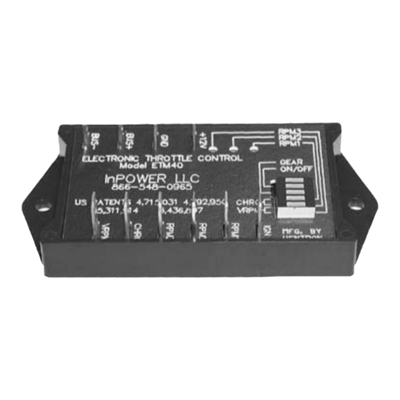
ETM40B/C
RPM1
Electonic
Throttle
Red/Light Green
RPM2
Module
Black
Tan/Orange
RPM3
+12V
GROUND
BUS+
CHRG
BUS-
VRPM
Pink/
Light Blue
Wire Harness (5 fT.)
View looking into connector
BUS- (Pink/Light Blue)
BUS+ (Tan/Orange)
Ground (Black)
+12V Power (Red/Light Green)
Note - On Excursion chassis with the diesel engine a special cable must
be used as Ford does not provide the above connector. The other cable connects to the
OBD-II diagnostic connector.
Mechanical Drawing
4.00
3.50
ETM40B
(Faston terminals not shown)
All dimensions in inches. Not to scale.
Contact Us:
InPower, LLC
PO Box 2520
Westerville, OH 43086
Tel: 740-548-0965 Fax: 740-548-2320
www.InPowerDirect.com
ETM40B/C Owner's Manual
Document: OM-03
Date: Oct 15, 2009
© Copyright 2014 InPower LLC
4
FUSE
+12 Volts
RPM 1
RPM 2
RPM 3
CHARGE (ETM40B Only)
RPM
CONTROL
GROUND
FORD
Engine Controller
0.1875
2.05
1.025
0.50
Version Code: H
Date: Oct 27, 2014
OWNERS MANUAL
Model ETM40B/C
Electronic Throttle Module
Ford 6.0 & 7.3 Liter Diesel Truck Engines
Introduction
Model ETM40B and ETM40C Electronic Throttles are designed to support
trucks that use Ford 6.0 & 7.3 liter turbo disel engines. Mode selection is
via fi ve inputs, and mode priority interlocking is provided.
The model ETM40B contains the Charge Protect mode and supports both
automatic and manual transmissions on the 7.3L engine applications. It
supports only manual transmissions on the 6.0L engine applications.
The model ETM40C does not contain the Charge Protect mode and
supports both automatic and manual transmissions on 6.0L engine
applications. It supports only automatic transmissions on 7.3L engine
applications.
Standard Features
•
Supports Ford 6.0 & 7.3L Power Stroke diesel engines
•
Multiple modes of operation
•
Direct interface to engine controller
•
Licensed Ford patented technology assures compatibility and
reliability
•
Encapsulated electronics for maximum environmental protection
•
LED status indicators
ETM40B/C Owner's Manual
Document: OM-03
Date: Oct 15, 2009
© Copyright 2014 InPower LLC
1
for
Version Code: H
Date: Oct 27, 2014
Advertisement
Table of Contents

Related Manuals for InPOWER ETM40B/C

Summary of Contents for InPOWER ETM40B/C
- Page 1 ETM40B/C Owner’s Manual ETM40B/C Owner’s Manual Document: OM-03 Version Code: H Document: OM-03 Version Code: H Date: Oct 15, 2009 Date: Oct 27, 2014 Date: Oct 15, 2009 Date: Oct 27, 2014 © Copyright 2014 InPower LLC © Copyright 2014 InPower LLC...
- Page 2 ETM40 data cable. A special data cable must be used that will connect to the RPM Range: 1200 to 2600 RPM vehicle’s OBD-II Data Link Connector. Contact InPower, LLC for details. D.Mode Priorities: Setup and Calibration RPM1 Highest - will override all other modes...
Need help?
Do you have a question about the ETM40B/C and is the answer not in the manual?
Questions and answers