Advertisement
Quick Links
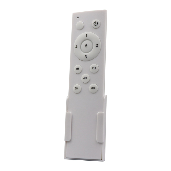
Transmitter Functions
Fan Off
1. Fan On - Slow
2. Fan On - Low
3. Fan On - Medium
4. Fan On - Medium High
5. Fan On - High
Transmitter & Receiver
Pairing
Pairing
1 Transmitter to 1 Receiver
1.
Switch ON the Isolator/Light Switch for the fan.
2.
Within 30 seconds of switching the Isolator/Light Switch
ON, press the FAN OFF button until the fan starts rotating.
3.
Pairing is now complete.
Pairing
1 Transmitter to Multiple Receivers
1.
Each fan must be paired individually and must have its
own Receiver and own Isolator/Light Switch.
2.
Start pairing by switching the Isolators/Light Switches OFF
for all the fans.
3.
Switch ON the Isolator/Light Switch for the fan you
are pairing.
4.
Within 30 seconds of switching the Isolator/Light Switch
ON, press the FAN OFF button until the fan starts rotating.
5.
Pairing is now complete for that fan.
6.
Switch OFF the Isolator/Light Switch for the fan you have
just paired, this will store it to memory.
7.
Move to the next fan, using the same Transmitter,
perform points 1 to 5 to pair the 2nd fan. Use this method
to pair each fan until all fans are paired.
Important
1.
The Isolator/Light Switch for the fans that have already
been paired must be in the OFF setting to retain the
memory.
2.
Pairing of 1 Transmitter to Multiple Receivers cannot
happen if all the fans are connected to one Isolator/
Light Switch. In this scenario a multiple fan wall controller
can be used instead of a Remote Control.
Timer Function
1.
There are 5 Timers – 1 hour, 2 hours, 4 hours, 6 hours
and 8 hours.
2.
The Timer must be set while the fan is in rotation
and it can be set on any speed.
3.
Press the desired Timer to put the fan in sleep mode and
the fan will turn off when the selected Timer is reached.
Receiver Connection
1.
Connect the RECEIVER as shown in wiring diagram.
Receiver Placement
1.
Once the connection is made, place the RECEIVER in
the canopy, slide the canopy up and tighten in position.
Receiver Memory Function
1.
After a power outage or a tripped circuit breaker,
the fan will default to Fan ON. The fan will run at the
speed that was last saved in memory.
t +27 (0) 31 563 4600 | info@solent.co.za | www.solent.co.za
RemoteF5
RemoteF5
- Fan Five Speed only
Indicator
Light
Fan Timers
1 to 8 hours
(Single Fan)
(Multiple Fans)
(Mains/Live)
Receiver
TRANSMITTER
Fan Off
Fan On - Slow
Fan On - Low
Fan On - Medium
Fan On - Medium High
Fan On - High
Installation of
Transmitter Wall Mount
Holder with two screws
RECEIVER CONNECTION
AC Power Supply
RED
BLACK
(Mains/Neutral)
Antenna
BLACK
WHITE
(Fan/Live)
RECEIVER PLACEMENT
WIRING DIAGRAM
To fan/LIVE
To fan/NEUTRAL
BLACKR
ED
NL
AC Power Input
Antenna
IMPORTANT POINTS
Caution:
1.
Do not use this
product in conjunction with
any wall/speed regulator.
2.
Please note that all fixed
wiring appliances should
be installed by a qualified
electrician.
3.
The supply to the remote
control receiver should be
connected through a mains
switch, i.e. existing wall switch.
4.
Disconnect from power supply
at wall switch before working
on remote control receiver or
ceiling fan.
5.
This unit is to be used for the
control of ceiling fans and in
an AC230/240V 50Hz power
supply only.
6.
The remote receiver must be
used within its load rating of
100 watt maximum.
7.
Do not install in damp
locations or immerse into
water. (For indoor use only.)
8.
The batteries will weaken with
age and should be replaced
before leaking takes place
as this will damage the
transmitter.
Overload Protection
for Fan Motor
If your fan or light suddenly goes
off, check the protection fuses.
WHITE
L
BLACK
N
Connection Block
on Fan Motor
8.20
Advertisement

Related Manuals for Solent RemoteF5

Summary of Contents for Solent RemoteF5
- Page 1 Fan ON. The fan will run at the BLACK AC Power Input speed that was last saved in memory. Antenna Connection Block on Fan Motor Receiver 8.20 t +27 (0) 31 563 4600 | info@solent.co.za | www.solent.co.za...
- Page 2 After a power outage or a tripped circuit breaker, the fan will default to Light OFF and Fan ON. The fan will run at the speed that was last saved in memory. 8.20 t +27 (0) 31 563 4600 | info@solent.co.za | www.solent.co.za...
- Page 3 After a power outage or a tripped circuit breaker, the fan will default to Light OFF and Fan ON. The fan will run at the speed that was last saved in memory. 8.20 t +27 (0) 31 563 4600 | info@solent.co.za | www.solent.co.za...
Need help?
Do you have a question about the RemoteF5 and is the answer not in the manual?
Questions and answers