Table of Contents

Related Manuals for FJDynamics FJD 3D


Summary of Contents for FJDynamics FJD 3D
- Page 1 Hardware Installation Manual for FJD 3D Excavator Guidance System FJD 3D Excavator Guidance System Hardware Installation Manual FJ Dynamics Technology Co., Ltd. Copyright © FJ Dynamics Technology Co., Ltd. All Rights Reserved.
- Page 2 Hardware Installation Manual for FJD 3D Excavator Guidance System Disclaimer The products, services, or features you purchase are subject to commercial contracts and terms thereof. All or part of the products, services, or features ◆ described herein may be excluded from the scope of your purchased or used products, services, or features. Unless otherwise agreed in the contract, FJD makes no statement, expressed or implied, with respect to this document.
- Page 3 Hardware Installation Manual for FJD 3D Excavator Guidance System Foreword Thank you for using the products of FJ Dynamics Technology Co., Ltd. This manual covers detailed hardware installation instructions. If you encounter any problems in the process of using this manual, please contact the FJD customer service, and we will serve you wholeheartedly.
-
Page 4: Table Of Contents
Hardware Installation Manual for FJD 3D Excavator Guidance System Contents I. Introduction ............................ 1 1.1 Main Hardware and Specifications ..................1 1.2 Main Performance Parameters ....................3 2. Preparation before Installation ....................3 2.1 Safety Instruction........................3 2.2 Requirements for Installation Site..................4 2.3 Installation Tools ........................ -
Page 5: Introduction
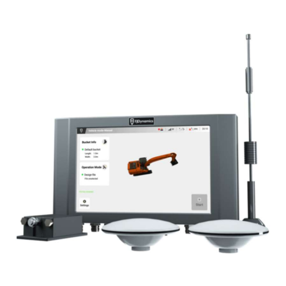
Hardware Installation Manual for FJD 3D Excavator Guidance System I. Introduction FJD 3D Excavator Guidance System is a rear-mounted excavator guidance system, which adopts Beidou high-precision real-time dynamic positioning technology. It gets the real-time precise 3D position information of the bucket by reading attitude sensors installed on the excavator and calculating the calibrated main pivot sizes. - Page 6 Hardware Installation Manual for FJD 3D Excavator Guidance System Relative humidity: 0%~95%, at 40 ℃ (non- condensation ); Wi-Fi specification: 2.4GHz frequency band; Frequency range: 2.4GHz~2.5GHz; output power: 14dB±1.5dB; Frequency range: GPS L1/L2, GLONASS L1/L2, BDS B1/B2/B3; GNSS Operating voltage: 3.3V~12V;...
-
Page 7: Main Performance Parameters
Hardware Installation Manual for FJD 3D Excavator Guidance System Max Angular Rate: ≤400⁰/s; Static Accuracy: 0.15°; Dynamic Accuracy: 0.50°; Temperature Stability:0.05°; Axes (Acceleration): X,Y,Z; Range: ±78m/s/s; Resolution: 0.01m/s/s; Accuracy: ±0.1m/s/s; Output Data Rate (Hz): Selectable to 100 Hz; Operating voltage: 4.9V~32V;... -
Page 8: Requirements For Installation Site
Hardware Installation Manual for FJD 3D Excavator Guidance System 2. Don’t install the equipment in places where water accumulation, water seepage, dripping, and moisture condensation most likely happen. 3. Install or remove the equipment as described in the hardware installation manual. -
Page 9: Installation Tools
Hardware Installation Manual for FJD 3D Excavator Guidance System around to facilitate heat dissipation. Temperature and Humidity Requirements 1. To ensure the normal operation and the service life of the equipment, temperature and humidity in the operating environment should be up to standard. -
Page 10: Open-Package Inspection
Hardware Installation Manual for FJD 3D Excavator Guidance System Assembly Tools for FJD 3D Excavator Guidance System Tool Model Function Cross Install control terminal and bracket base Mid-size screwdriver plate Hex key set T3~T6 Install attitude sensor, bracket screws, etc. -
Page 11: Installation
Hardware Installation Manual for FJD 3D Excavator Guidance System Protective cover for sensors Hexagon socket head cap screw M5×12 Hexagon socket head cap screw M10×25 Pan head bolt with elastic flat washer M6×14 Hexagon Nut Class 1 Standard Spring Washer φ10... -
Page 12: Check Before Installation
Hardware Installation Manual for FJD 3D Excavator Guidance System Please be sure that you have carefully read the content of Chapter 2 and that the requirements described in Chapter 2 have been met. 3.1 Check before Installation Before installation, make thorough plans and arrangements for the installation location, power supply, and wiring of the equipment. -
Page 13: Installation Process
Hardware Installation Manual for FJD 3D Excavator Guidance System 3.2 Installation Process Start Unpack and check the Contact our dealers for list of incoming materials replenishment Incoming materials are complete Select the installation Determine where to Assemble the attitude Assemble the RTK... -
Page 14: Precautions For Installation
Hardware Installation Manual for FJD 3D Excavator Guidance System 3.3 Precautions for Installation 1. Do not power on the equipment when installing it. 2. Place the equipment in a well-ventilated environment. 3. Avoid placing the equipment in a high temperature environment. -
Page 15: Installation Steps
Hardware Installation Manual for FJD 3D Excavator Guidance System 4.1.2 Installation Steps Step 1: Fix the base. Choose the round steel position on the door side of the cab for easy operation (depending on model structures). After determining the installation position, fix the bracket base of control terminal with U-bolts and nuts. -
Page 16: Installation Of Attitude Sensor
Hardware Installation Manual for FJD 3D Excavator Guidance System 4.2 Installation of Attitude Sensor 4.2.1 Required Materials Name Quantity Spec./model Remark Attitude sensor Attitude sensor mount Protective cover for sensor Hexagon socket head cap M5x12 screw Hexagon Nut Class 1 3M VHB double-sided tape 4.2.2 Installation Steps... - Page 17 Hardware Installation Manual for FJD 3D Excavator Guidance System This sensor is intended to realize terrain data compensation to ensure the accuracy of the excavator in operating environments such as slopes, foundation pits, and water. (2) Attitude Sensor (Boom) This sensor is intended to monitor the boom extension angle and judge the boom angle in real time.
- Page 18 Hardware Installation Manual for FJD 3D Excavator Guidance System (3) Attitude Sensor (Arm) This sensor is intended to monitor the arm extension angle and judge the arm angle in real time. (4) Attitude Sensor (Bucket) This sensor is intended to monitor the bucket extension angle and judge the bucket angle in real time.
-
Page 19: Installation Of Antenna
Hardware Installation Manual for FJD 3D Excavator Guidance System 4.3 Installation of Antenna 4.3.1 Required Materials Item Spec./model Remark RTK antenna 4G sucker antenna RTK bracket RTK bracket base Antenna convertor Hexagon socket head cap M10×25 screw Pan head bolt with elastic... - Page 20 Hardware Installation Manual for FJD 3D Excavator Guidance System 2. Install the RTK antenna on top of the mounted bracket, and ensure that the threads are tightened. 3.Weld RTK bracket base to two symmetrical positions respectively on both end of excavator backside.
-
Page 21: Installation Of Harness
Hardware Installation Manual for FJD 3D Excavator Guidance System 4.4 Installation of Harness 4.4.1 Required Materials Item Spec./model Remark Smart main harness Power harness Attitude sensor harness Strap Several Strap fixing base Several 4.4.2 Installation Steps 1. Installation of Sensor Harness... - Page 22 Hardware Installation Manual for FJD 3D Excavator Guidance System 2. Installation of Power Harness A spare power line is needed for the extension of the power line if it’s not long enough. The positive terminal buckle of the power line must be screwed to the positive terminal of the relay, and the negative terminal to the cathode of the battery.
-
Page 23: Installation Of Sim Card
Hardware Installation Manual for FJD 3D Excavator Guidance System 4. Installation of Control Terminal Interface Connect the main harness interface, two RTK antennas (the Beidou1 interface is for the positioning antenna, and the Beidou2 interface is for the directional antenna), and the 4G antenna in turn. Turn on the power harness switch to check whether the power indicator of control terminal comes on and start control terminal to check whether it works normally. -
Page 24: Installation Steps
2. Place the SIM card with the chip facing upwards, use an ejector needle and tweezers to slowly insert the SIM card into the proper position of the slot in the top T3 interface. As above, the hardware part of FJD 3D Excavator Guidance System has been installed. 5. System Commissioning 5.1 Check before Commissioning... -
Page 25: Power-On And Startup
2. After pressing the switch of control terminal, please check if control terminal program can be started normally. 5.3 Specification Commissioning Please refer to the Software Instruction Manual for FJD 3D Excavator Guidance System attached to the machine for details of the parameter Commissioning. Copyright © FJ Dynamics Technology Co., Ltd. All Rights Reserved.
Need help?
Do you have a question about the FJD 3D and is the answer not in the manual?
Questions and answers