
Related Manuals for FJDynamics FJNBD-2.5RD


Summary of Contents for FJDynamics FJNBD-2.5RD
- Page 1 FJDynamics Autosteering Kit Software User Manual FJNBD-2.5RD ©FJ Dynamics Technology Co., Ltd. All rights reserved. ©FJ Dynamics Technology Co., Ltd. All rights reserved.
- Page 2 ©FJ Dynamics Technology Co., Ltd. All rights reserved.
- Page 3 Safety Instructions Before using this FJDynamics Autosteering Kit (shorten as the kit), please read the entire contents of the “FJDynamics Autosteering Kit Software User Manual” carefully, and keep in mind when operate it. Operator Requirements 1. Persons under the age of 18 are prohibited from operating.
- Page 4 3. When the vehicle equipped with this kit is driving on public roads or public areas, please ensure that the kit is powered off. Checking 1. Make sure to have enough fuel in the driving vehicle. 2. Ensure that the parameters in the kit are calibrated before the automatic driving operation.
-
Page 5: Table Of Contents
Contents Chapter I About This Document..............1 1 Purpose....................1 2 Technical Support................1 Chapter II Product Overview................2 1 Introduction..................2 2 Main Components................2 3 Hardware Interface Description of Control Terminal......4 Ⅲ Chapter Software Operation Instructions of Control Terminal ....5 1 Workflow Overview................5 2 Commissioning...................5 2.1 Selecting a Language..............6 2.2 Register/Login................6 2.3 Entering Installation Information..........7... - Page 6 3.2.1 Confirm RTK Connection..........40 3.2.2 Add and Select Fields.............40 3.2.3 Add and Select Boundary..........42 3.2.4 Add and Select Guidance Line........46 3.2.5 Add and Select Task Setting..........47 3.2.6 Confirm Task Configuration..........48 4 Start Operation..................49 4.1 Operation Interface..............49 4.2 Operation Setting..............50 5 Other Functions................56 5.1 Status..................56 5.2 Location History................57 5.3 Settings..................58...
-
Page 7: Chapter I About This Document
Chapter I About This Document 1 Purpose This document describes how to use the FJDynamics autosteering kit for agricultural vehicles. The language used in the document is concise, and the operation process is simple and clear, so that the user can learn to perform each operation easily, quickly and accurately. -
Page 8: Chapter Ii Product Overview
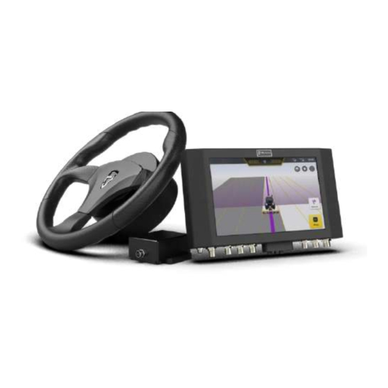
Chapter II Product Overview 1 Introduction Launched by FJ Dynamics, FJDynamics Autosteering Kit for agricultural vehicles supports assistant straight driving and fully unmanned transformation. The kit can not only control the steering to provide driving assistance for the vehicle, but also realize the fully unmanned transformation of agricultural vehicles through the control of the vehicle's accelerator, brake, clutch, gearbox, and operation components. - Page 9 2. Steering Wheel It provides steering control in vehicles. 3. Angle Sensor It monitors the wheel rotation angle to determine the direction of the vehicle in real-time. 4. IMU All-terrain data compensation is achieved to ensure the accuracy of agri- robots in sloping fields and high-speed operating environments.
-
Page 10: Hardware Interface Description Of Control Terminal
maintain a good ventilation environment. 3 Hardware Interface Description of Control Terminal Figure 2.3.1 Hardware interface description of control terminal ©FJ Dynamics Technology Co., Ltd. All rights reserved. -
Page 11: Chapter Software Operation Instructions Of Control Terminal
2 Commissioning The initial commissioning process of FJDynamics Autosteering kit is as follows: Select a language → Register and log in to your account → Enter installation information →... -
Page 12: Selecting A Language
2.1 Selecting a Language Turn on the in-vehicle control terminal and select a language for this kit. tap Next step. The screen for registration and login is displayed. Figure 3.2.2 Selecting a language 2.2 Register/Login After completing the language settings, you will enter the registration and login screen. -
Page 13: Entering Installation Information
Figure 3.2.3 Home screen of login and registration 2.3 Entering Installation Information After successfully registering and logging in for the first time, you need to enter related installation information, user information and Auto-kit information. Please note that the initial information you have entered will directly or indirectly affect your after-sales service. - Page 14 Figure 3.2.4 Entering user information Step 2 : Enter this information and tap Next step. The screen for entering agricultural vehicle information is displayed. Figure 3.2.5 Entering Auto-kit information Step 3:Specify all parameters about the agricultural vehicle and tap Next step.
- Page 15 After you select a type of the vehicle, the kit will directly enter the corresponding agricultural vehicle kit. Please select the type of the vehicle you will actually use. Figure 3.2.7 Selecting system mode Step 4: In terms of system mode, select the corresponding one. Please choose carefully according to the actual usage and tap Save.
-
Page 16: Home Screen
2.4 Home Screen After successfully logging in to the system, you will enter the home screen. You can view the network connection status and operation status in real time. Your account login record will be automatically saved locally. Therefore, you can directly enter the home screen of the kit every time you open the kit. - Page 17 6. RTK signal: The carrier phase differential signal. It includes two modes of the portable base station and network RTK, showing the differential signal strength in real-time. 7.Time: Android system time, users can manually changed the time zone in Android system. 8.
-
Page 18: Main Interface Of Advanced Mode
2.4.2 Main Interface of Advanced Mode Figure 3.2.9 Main interface of advanced mode 1. Current driving mode:Shows the current driving mode, including manual driving mode and autosteering driving. 2. WiFi signal: Show that the current device is connected to the wireless network. -
Page 19: Connecting To Rtk
8. Perspective switch: Fix the perspective of three-dimensional view by tapping the button. 9. Real-time video: Real-time monitoring of machine tool operation status through Wi-fi camera, real-time feedback of operation status. (Note: Wi-fi camera needs to be purchased separately.) 10. Status: Tap to access the real-time information and current status of agricultural machines. - Page 20 Figure 3.2.10 Settings list Step 2: Select the RTK connection mode you want to use. Figure 3.2.11 Connecting to RTK This kit can be connected to base station RTK or Internet RTK. The kit is connected to a mobile base station by default. You can switch the connection mode by using the Enable/Disable switch.
- Page 21 If you want to connect mobile base station RTK, please enable Mobile Base Station. Then, tap Frequency Connecting. In the displayed dialog box, enter the required frequency code of the connected base station. (For details about the rules for entering the base station's frequency code, refer to the Base Station User Manual.) Figure 3.2.12 Entering the frequency code ...
- Page 22 Password after specifying Ntrip domain information. Then, tap Connect to connect to the corresponding Internet RTK. Figure 3.2.13 Connect Network RTK Notes for RTK connection: 1. It will take up to 3 minutes to connect to the frequency of base station, and please be patient.
- Page 23 Figure 3.2.14 Setting list Troubleshooting: The troubleshooting detection is divided into two states, the green one means passing the test, and the red one means failing. Figure 3.2.15 Troubleshooting ©FJ Dynamics Technology Co., Ltd. All rights reserved.
-
Page 24: Setting Vehicle Parameters
2.6 Setting Vehicle Parameters After entering the home screen of the kit, perform the following operations to set vehicle parameters: From the sidebar, choose Settings -> Vehicle Information. Figure 3.2.16 Setting List Figure 3.2.17 Vehicle information ©FJ Dynamics Technology Co., Ltd. All rights reserved. -
Page 25: Calibratig Angle Sensor
*For details about the measurement operations, please check the corresponding commissioning instruction video. 2.7 Calibrating Angle Sensor After completing vehicle parameter settings, you need to calibrate the angle sensor. Perform the following operations to calibrate the angle sensor: Step 1: Choose Settings -> Parameter Settings. Figure 3.2.18 Setting list Step 2: Tap ”Angle Sensor Calibration”... - Page 26 Figure 3.2.19 angle sensor calibration Step 3: User needs to select the sensor type after getting into the angle sensor setting page. Figure 3.2.20 Select angle sensor type If the selected type is "Hall Sensor", then the user needs to select the installation position of the angle sensor.
- Page 27 according to the process "leftmost-rightmost-center" and tap “OK” after each action finished. Figure 3.2.21 Turning the wheel to the leftmost Figure 3.2.22 Turning the wheel to the rightmost ©FJ Dynamics Technology Co., Ltd. All rights reserved.
- Page 28 Figure 3.2.23 Turning the wheel to the center If the angle sensor type is selected as "attitude sensor", please then select the installation position of your angle sensor. Note: when you choose “attitude sensor”, you shoule drive straight for 15-20m in manual mode to complete data convergence everytimes you open the system.
- Page 29 Figure 3.2.25 No angle sensor After entering the setting screen for no angle sensor, put the vehicle’s gear into the low gear first. Then, tap Detect and step on the accelerator to make the agricultural vehicle run straight for about 20 m on a level surface freely at a low speed (2–3 km/h) until the Detection Succeeded prompt box is displayed.
-
Page 30: Vehicle Calibration
Figure 3.2.26 Detecting the speed ratio Figure 3.2.27 Detect finished If the sensor type is switched, the device needs to be restarted after the sensor is switched to take effect. 2.8 Vehicle Calibration After angle sensor calibration finished, you need to calibrate vehicle to correct working offset . - Page 31 Figure 3.2.28 Setting List Step 2: Tap into “Vehicle Calibration” in the parameter page. Figure 3.2.29 Vehicle Calibration Step 3: Tap “Start Calibration” in the vehicle calibration page, and then getting into the calibrating process. ©FJ Dynamics Technology Co., Ltd. All rights reserved.
- Page 32 Figure 3.2.30 Start Calibration Step 4: On the calibration screen, carefully read the current calibration step displayed. Then, determine Points A and B exactly as prompted on the screen. Move the agricultural vehicle to the starting point and tap Comfirm Point A on the screen.
- Page 33 and Comfirm Point B. Figure 3.2.32 Confirm Point B During the driving towards Point B, the distance traveled will be displayed on the upper right corner of the screen in real time. You can check whether the current distance from Point A meets the distance requirement of 50m based on this value.
- Page 34 Figure 3.2.33 Starting auto steering driving after turning around Step 7: tap Stop after the vehicle arrives at Point A in the autosteering driving mode. Figure 3.2.34 Stopping auto steering driving Step 8: Manually turn the vehicle around to make it return to Point A on the guidance line (with the front end of the vehicle facing Point B).
- Page 35 Figure 3.2.35 Manually turning around and start the auto-working Step 9: After the vehicle reaches Point B in the auto steering driving mode, tap Stop to stop the current auto steering driving operation. Figure 3.2.36 Stop autosteering driving after reaching the point A Step 10: tap Calibrating completed to complete the vehicle calibration and return to the home screen.
-
Page 36: Preparatory Operations
Figure 3.2.37 Calibration finished After completing the above steps of commissioning, you can start to use control terminal for intelligent operations. 3 Preparatory Operations 3.1 Preparatory Operation in Fast Mode Confirm RTK connection → Add guidance line → Import guidance line → Start operation Figure 3.3.1 Preparatory operation procedure ©FJ Dynamics Technology Co., Ltd. -
Page 37: Check Rtk Connection
3.1.1 Check RTK Connection Confirm the current connection to the RTK before performing preparatory operations. (1) Check whether the current RTK connection mode is correct. Figure 3.3.2 RTK Settings (2) Check whether the current RTK connection is stable. Figure 3.3.3 Home page ©FJ Dynamics Technology Co., Ltd. -
Page 38: Adding New Guidance Line
Check if the RTK signal display in the status bar is full, or if RTK Status in Real-time Status is 4. 3.1.2 Adding New Guidance Line After confirming the connection to the RTK, you can start setting points. You can follow the prompts to complete setting points A and B to save a new guidance line, and import the new guidance line to the current operation, as follows: ... - Page 39 Figure 3.3.5 Guidance Line List Step 2: Move the vehicle to the starting point of the operation, and tap Confirm Point A on the screen of control terminal to determine the current position as Point A of the new guidance line. After confirming Point A, manually drive the vehicle straight for 15–20 m.
- Page 40 Figure 3.3.7 Confirming Point B Step 4: After confirming Point B, please tap “Import” and enter the guidance line name in the prompt. Then go back to the list of guidance lines after naming the new line. And the newly added guidance line will be displayed on the top of the list.
- Page 41 Step 1: Tap "New Guidance Line" in the home page to start the procedure for creating a new guidance line. Figure 3.3.9 Home Page Or tap the sidebar "Guidance Line" to expand the guidance line details page, and tap "Add" in the interface on the guidance line details page to start the process of creating a new guidance line.
- Page 42 Step 2: On the displayed Guidance Line setting page, tap Straight Line to switch the plotting mode to the curve. Figure 3.3.11 Switch plotting mode to the curve Step 3: After switching to the curve mode, please move the vehicle to the starting point of the operation, and tap Confirm Point A on the screen to confirm the current position as Point A on the curvilinear guidance line.
- Page 43 Step 4: After confirming Point A, please directly curve the vehicle’s path to the ending point of another side you want to determine (for example, from the starting point to the other field edge) in manual mode and tap Comfirm Point B. Figure 3.3.13 Comfirming Point B Notes for the curve mode: 1.
-
Page 44: Import Guidance Line
Figure 3.3.14 Import new guidance line Step 6: The kit will automatically import this curvilinear guidance line to the current operation, as shown in the following figure Figure 3.3.15 Auto-working in Curve mode 3.1.3 Import Guidance Line You can directly import the required guidance line from the list of guidance lines to the current operation as follows: Step 1: If you have already saved the guidance line before, please find out ©FJ Dynamics Technology Co., Ltd. - Page 45 the line you want to import in the list of guidance lines. And then tap Import buttom in the required guidance line tab to import the line to the current operation. Figure 3.3.16 Guidance line list If Multi Line Mode is needed, please enter into Settings -> Parameter Settings ->...
-
Page 46: Preparatory Operation For Advanced Mode
Figure 3.3.18 Guidance line imported 3.2 Preparatory Operation for Advanced Mode Confirm RTK connection → Add and select field → Add and select boundary → Add and select guidance line → Add and select task setting → Confirm task configuration → Start operation Figure 3.3.19 Preparatory operation flow chart 3.2.1 Confirm RTK Connection Before preparing the operation, please confirm the current RTK connection. - Page 47 add and select an operation field. Figure 3.3.20 Task configuration entry The configuration field interface is shown in the figure below: Figure 3.3.21 Configure field interface 1. Task configuration items: Select the field, boundary, guidance line and task settings required for the operation. Yellow represents the current configuration items.
- Page 48 been selected, it will display "not selected". Otherwise, the corresponding option is displayed below. 2. Search box: Find the target field by searching the field name. 3. Field list: Display existing fields, including field name and creation time. Click to select the field to be operated. 4.
-
Page 49: Add And Select Boundary
Figure 3.3.22 Interface for adding field 3.2.3 Add and Select Boundary Click boundary item to add and select the boundary required by the operation in the list. If the operation does not require a boundary, user can select the "No boundary" option. The configuration boundary interface is shown in the figure below: Figure 3.3.23 Interface for configuring boundary ©FJ Dynamics Technology Co., Ltd. - Page 50 1. Boundary list: Display the existing boundary, including name of boundary, the workable area enclosed and the creation time. 2. Delete boundary: After selecting the boundary, click "Delete" icon, and the deleted items can be restored in the recycle bin within 30 days after deletion. For details about the recycle bin, please refer to the introduction of the recycle bin in 5.3.7 System Settings.
- Page 51 Figure 3.3.25 Interface for completing boundary recording When saving, it is required to fill in the boundary name, the distance between the field and the boundary, and the positional relationship between the field and the boundary, and then save the boundary after filling in. Figure 3.3.26 Save boundary interface When the recording is completed and click “save”, if the distance between the beginning and the end of the boundary is less than 10m, the system will...
-
Page 52: Add And Select Guidance Line
If 10m<distance between the beginning and the end of the boundary <50m, and user confirms to save the boundary, the system will connect the beginning and the end of the boundary with a straight line. If the distance between the beginning and end of the boundary is greater than 50m, it is impossible to save and should continue to record the boundary. -
Page 53: Add And Select Task Setting
Figure 3.3.27 Interface for configuring guidance line 1. The guidance line list of the field: Display the existing guidance lines, including the name, length and creation time of the guidance line. 2. List of guidance lines without attribution: Display the guidance lines generated in the extreme Fast Mode. - Page 54 Figure 3.3.28 Setting Interface for configuring operation 1. Task settings list: Task settings that has been created. 2. Delete task setting: Delete the selected task setting, which cannot be restored after deletion. 3. Modify task setting: Modify the operation type and operation width of the selected task setting.
-
Page 55: Confirm Task Configuration
3.2.6 Confirm Task Configuration After all the information are selected, Click confirm button, and an information confirmation window will pop up. After confirming that the configuration information is correct, click “OK”. Click "Start " button on the homepage to enter the operation interface. Figure 3.3.30 Interface for confirming configuration 4 Start Operation 4.1 Operation Interface... -
Page 56: Operation Setting
Figure 3.4.1 Operation interface 1. Operation record button: Yellow means that the current operation data is recording. And white means that the current operation data is not recorded. Click to switch the recording status. 2. Auto-driving button: Yellow means it is in auto-driving status. White means it is not in auto-driving status.Click to switch driving status. - Page 57 (1) Switch operation record status Click "Start Recording/Recording" button in the lower left corner of the main interface to switch the status of the operation record. Non-recording operation status: The operation data and operation traces during the non-recording time are not recorded in this operation. Record operation status: operation data and operation traces during the recording time are recorded in this operation.
- Page 58 Figure 3.4.2 Selecting shifting method of guidance line In the manual mode after starting the task, the user adjusts the guidance line in the current multi-line mode to the left and right according to the needs of the actual operation, and drives according to the adjusted guidance line. 1.
- Page 59 Figure 3.4.3 Shift guidance line 2. Shift the guidance line to the current position. Click "Shift to current position" in the operation setting to move the guidance line to the position of the agricultural machine. 3. Offset adjustment. Click "Offset fine-tuning" button in the operation setting, the user can shift the current guidance line to the left and right according to the actual operation needs, and click "√"...
- Page 60 Figure 3.4.4 Offset correction Note for The Use of Shifting Guidance Line: Shift guidance line function is available only in the manual driving status in the multi-line mode. (4) Switch operation mode The operation mode is divided into single-line mode and multi-line mode. The user can click "multi-line mode/single-line mode"...
- Page 61 Figure 3.4.5 Multi-line mode Figure 3.4.6 Single-line mode ©FJ Dynamics Technology Co., Ltd. All rights reserved.
- Page 62 (5) Mark the Edge Figure 3.4.7 Marking the field edge After importing guidance line or during the intelligent operation, you can enable the function of marking the field edge according to the actual needs. This function can alert the user when the vehicle is about to reach the field edge of another side, thereby effectively avoiding safety accidents especially in dark environment.
-
Page 63: Other Functions
In addition to completing commissioning and autosteering operations, you also can check the real-time status of the operating vehicle and undertake other system settings on the in-vehicle control terminal. 5 Other Functions 5.1 Status Figure 3.5.1 Status Users click the "Status" to access the working status and operation of the vehicle. -
Page 64: Location History
Park brake: Emergency braking; RTK status: The current status of RTK connection. The RTK connection is very stable when it shows the value of 4, otherwise, please check the working environment. Motor status: The status of the motor; Motor error code: the error number when an error occurs; 5.2 Location History Figure 3.5.2 Operation Data 1. -
Page 65: Settings
Precautions of operation data: 1. Historical operation data is the operation data accumulation of each Guidance line. 2. The latest operation is placed on the top of the list, sorted by date. 3. The date on the list is the date on which the field was saved, not the date of the last job operation. -
Page 66: Rtk Settings
5.3.1 RTK Settings Figure 3.5.4 RTK Settings RTK is such a technology that can ensure a centimeter-level high-precision positioning of the agricultural machinery. There are network RTK and mobile base station. Network RTK is provided by local telecom operators, while mobile base station service needs to purchase FJD base stations. -
Page 67: Working Width Alerts
5.3.2 Working Width Alerts Figure 3.5.5 Working width alerts On the displayed Parameter Settings screen, tap the Working width Alerts tab. The displayed details screen allows setting Operating space, Speed Alert, Offset Range Alert, and Driving distance warning. tap the item that needs to be set and enter the corresponding value. - Page 68 Settings-Accessibility. Figure 3.5.6 NMEA settings Data Transfer Step 1: Insert the mobile storage device into the T1 port above the vehicle display control terminal (the T1 port is a USB Type-C port, if the mobile storage device is a Type-A port, it is required to purchase a connector converter). Figure 3.5.7 Connection diagram of mobile storage device Step 2: Enter the data transfer interface, user can export map information ©FJ Dynamics Technology Co., Ltd.
- Page 69 USB, such as: fields, boundary, guidance line, mission data etc., for use by other terminals, and user can also import map information from other devices to FJDynamics Autosteering kit. Data information in some formats may not be imported. For details, refer to the description of the importable format displayed in the interface.
-
Page 70: Vehicle Parameters
5.3.4 Vehicle Parameters Figure 3.5.9 Vehicle parameter settings Tap the “Vehicle Parameters” tab. On the displayed details screen, tap the required items and enter the corresponding vehicle data to complete vehicle parameter settings. For specific measurement details, please refer to the instruction video. - Page 71 Figure 3.5.10 Positioning antenna spacing calibration Step 1: Create a guidance line: create and import a guidance line. (The starting point is point A, the end point is point B) Step 2: Set the line spacing and select the operation mode: set the operation spacing in the "parameter setting"...
-
Page 72: Parameter Setting
Step 4: Measuring error: use a tape measure to measure the distance between the two marking lines, and record the value a (unit: m) Step 5: Please enter a value in the interface of "Positioning Antenna-Central Axis Distance", and click "OK" to complete the corresponding positioning antenna spacing calibration. - Page 73 Figure 3.5.12 Settings for no angle sensor Calibration of Accessories Figure 3.5.13 Settings for calibration of accessories When autodriving path has a offset within 3 cm after the implement is equipped, please measure the value. If the autodriving path tends to the left comparing to the pre-set guidance line, please select "implement offset to the left"...
- Page 74 the autodriving path tends to the right, select "implement offset to the right" and enter the deviation value a, and click "OK". Parameters Commissioning (for FAE Only) Figure 3.5.14 Parameter settings Approach Aggressiveness: affects the time for the vehicle to enter the next guidance line when making a turn.
-
Page 75: Troubleshooting
Vehicle Calibration Figure 3.5.15 Vehicle calibration For detailed operations, see section 2.8 Vehicle Calibration in Chapter IV Software Operation Instructions of In-vehicle Control Terminal. 5.3.6 Troubleshooting Figure 3.5.16 Troubleshooting ©FJ Dynamics Technology Co., Ltd. All rights reserved. -
Page 76: System Settings
encountering problem during use, user enter “Troubleshooting” to perform software and hardware detection of the vehicle. The user can promptly adjust the fault items displayed as "×" in the screen, the interface is as shown in the figure above. 5.3.7 System Settings ... -
Page 77: Wifi Camera (Optional)
progress through the displayed information and wait for its completion. 5. After the upgrade is successful, the system will display a prompt that the upgrade is successful and then automatically enter the new version. 6. If the upgrade fails, the system will prompt you to retry. tap Retry to re- upgrade the system. - Page 78 required to bind other cameras, click “Delete” and repeat the binding steps to bind. Figure 3.5.18 WiFi camera configuration 4. After the binding is completed, user can click return button in the upper left corner to enter the working interface, and Click real-time video button to open the main interface display.
- Page 79 Figure 3.5.19 Real-time video 5.3.9 Remote Debugging Turn on the remote debugging function, which should use with the background control program to realize the remote control screen function; user should turn on the remote debugging switch in the settings. Figure 3.5.20 Remote commissioning ©FJ Dynamics Technology Co., Ltd.
-
Page 80: Other Settings
5.3.10 Other Settings In addition to Parameter Settings, RTK settings, and Troubleshooting, the Settings screen allows setting and querying other general information such as Volume, Brightness, and device information. ©FJ Dynamics Technology Co., Ltd. All rights reserved. -
Page 81: Chapter Ⅳ Faqs
Ⅳ Chapter FAQs Fault Troubleshooting Check if the rolling angle and pitching angle data changes in real time. "S" turn in autosteering Calibrate the angle sensor operations Check whether the GNSS antenna installation connector is correct. Check the brake status. Test the motor Power off and restart the vehicle. -
Page 82: Chapter Ⅴ Main Hardware And Its Specifications
entered correctly. Please verify that vehicle calibration in Settings spacing in multi- is completed. line mode Please re-calibrate the accessories. Chapter Ⅴ Main Hardware and its Specifications Assembly Components Specifications Control Control Size: 300×190×43mm; Terminal Terminal 10.1-inch capacitive touch screen, LED backlight, 1280*800 pixels, 700cd/m2 LCD;... - Page 83 WIFI specification: 2.4GHz frequency band, frequency range: 2.4GHz-2.5GHz, output power: 14dB±1.5dB Frequency range: GPS L1/L2, GLONASS L1/L2, BDS B1/B2/B3; GNSS Operating voltage: 3.3~12VCD; Antenna Operating current: ≤45mA; Size: 152*63mm Suction cup antenna: Frequency range: B1/B2/B3/B5/B8/B38/B39/B40/B41; VSWR: ≤2.0; 4G Antenna Gain (dBi): 2±0.5; Antenna Impedance (Ω): 50;...
- Page 84 Acceleration accuracy: 0.09mg; Gyroscope accuracy: 0.004°/s; Heading angle accuracy: 1°; Roll and pitch angle: 0.5° Power supply: 5V; Update frequency: typical 3.4KHz; Angle Angle Sensor Resolution: < 0.1°; Sensor IP rating: IP67; ℃ ℃ Operating temperature: -40 ~+85 Power supply: 12V/24V; Steering Peak torque: 20Nm (12V);...
Need help?
Do you have a question about the FJNBD-2.5RD and is the answer not in the manual?
Questions and answers
Схема подключения выносной кнопки автопилота