
Related Manuals for EPI LDS-910 Plus

Summary of Contents for EPI LDS-910 Plus
- Page 1 Leak Detection System LDS-910 Plus User Manual Revision 1.2 (20210803) Electric Power, Inc. 1351 West Hundred Rd. Chester, VA 23836 (804) 778-7735 info@elecpwr.com...
-
Page 2: Table Of Contents
Table of Contents Specifications ....................................3 System Description ...................................3 Unit Layout .......................................4 Test Frequencies ....................................6 Powering Up .....................................6 Default Settings ....................................7 Control Buttons ....................................8 Calibrating the LDS-910 Plus: ................................ 10 Test Procedure: ..................................... 11... -
Page 3: Specifications
Specifications System Operating Frequencies 400-960 MHz Transmit Power +30dBm (1 watt) 12 VDC, Center Positive Barrel Plug Transmitter Input Power Source AC Power adapter or (8) AA battery Pack Dynamic Range 110 dB @ 915Mhz Antenna Omni Directional, SMA, Standard Receiver Input Power Other Antenna Options Available Internal Lithium Battery, Rechargeable with USB... -
Page 4: Unit Layout
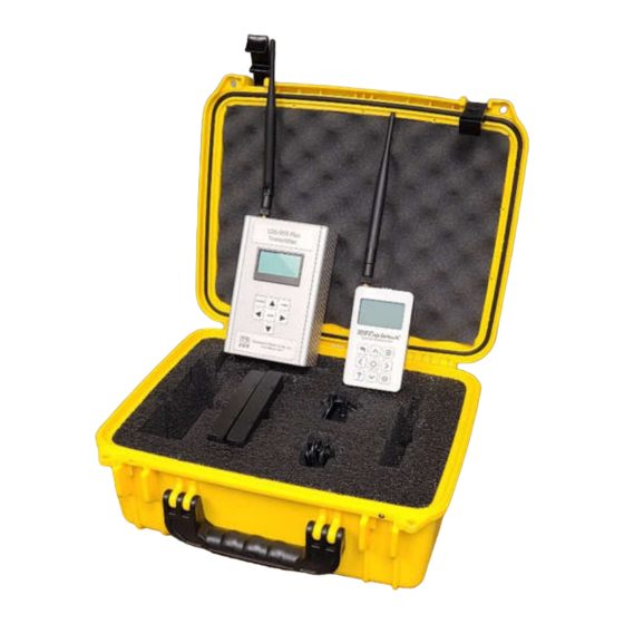
Unit Layout Figure 1 – Storage Case Layout Figure 2 – Receiver Layout... - Page 5 SMA Antenna RF Out 12VDC Power Input LCD Screen (On Rear) Control Buttons Figure 3 – Transmitter Layout Power Switch Figure 4 – Transmitter Battery Pack Power Switch Location...
-
Page 6: Test Frequencies
Test Frequencies The LDS-910 Plus can test in the frequency range of 400-960MHz. The included antennas however are tuned for the ISM band of 902-928Mhz. To test in other frequency bands, use the appropriate antennas. For other antenna options, please contact EPI for recommendations. -
Page 7: Default Settings
Default Settings When the unit is shipped to you, it is set to the default settings shown in the image below. The settings below are shown as a reference in case the user changes the settings. The calibration and test procedures shown below are based off the unit setup as shown in the following images. -
Page 8: Control Buttons
Control Buttons A diagram showing the function of each button on the receiver is shown below. RETURN Button MENU Button ENTER Button HELP Button PRESET Button Figure 6 – Receiver Button Layout... - Page 9 MENU Button RETURN Button ENTER Button Figure 7 – Transmitter Button Layout...
-
Page 10: Calibrating The Lds-910 Plus
Calibrating the LDS-910 Plus: The LDS-910 Plus Receiver can be calibrated to the transmitter with an offset value so it shows the shield effectiveness on the screen. These procedures will outline testing in the ISM band of 902-928Mhz. This procedure should be repeated every time the unit is used to ensure accurate readings. The calibration procedure is shown below. -
Page 11: Test Procedure
receiver can read from +30db to -90db. With the attenuator disabled, the unit will read from -10 dB to -120db. The transmitter will output at values greater than -10db, so unless the attenuator is enabled for calibration the value will not be shown. Similarly, if the attenuator is enabled while testing, the dynamic range will be severely limited.
Need help?
Do you have a question about the LDS-910 Plus and is the answer not in the manual?
Questions and answers