Advertisement
Quick Links
Advertisement

Summary of Contents for Verity Audio SM07F
- Page 1 7 INCH WATERPROOF QUAD MONITOR SYSTEM Part # SM07F Please read this manual completely before operating the SYSTEM A division of Component Solution Services, LLC. 56600 Twin Branch Drive Mishawaka, IN 46545 www.VerityRVs.com © Verity Rear Vision Systems All rights reserved 2019...
- Page 2 SM07F Component Solution Services LLC., offers the Verity Rear Vision System® to meet any requirement and price point within the trucking, specialty vehicles, and RV industry. Verity Rear Vision Systems® is also home to the Supreme View® line of specialty format systems. Our standard cabled systems offer unparalleled features into the trucking and RV industries.
- Page 3 Thank you for your purchase of our Verity Rear Vision Systems®. When installed and used properly, your SM07F is designed to deliver you years of trouble-free operation. This manual contains important information required to properly install and operate the unit.
- Page 4 Do not locate the monitor near heat generating vents or devices. Turn off power to the monitor when connecting the camera. Monitors are not designed to be waterproof. (Our SM07F waterproof monitor is the exception). Exposure to water, such as rain, may damage the unit.
-
Page 5: System Features
SYSTEM FEATURES MONITOR SPECIFICATIONS Screen size: 7-inch digital screen (16:9) Monitor is waterproof with IP 69 rating Long Life High Resolution: 800 ×480 Pixel (RGB) Contrast: 500:1 Brightness: 400cd/m2 Power: DC 12V~32V reverse polarity protection Operation temperatures: -20~70C Storage temperature: - 30~80C Easy to use OSD menu function via touch screen reversing image delay time 0~4s, (for side cameras) Mirror/Normal image, multi-... -
Page 6: System Components
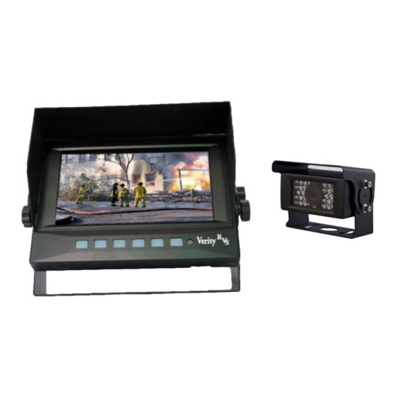
SYSTEM COMPONENTS I/F Remote 7 Inch IP 69 Monitor Panel Infrared Weatherproof Camera 20-Meter Camera Cable Sun Shield “U” Style Mount... -
Page 7: System Mounting
SYSTEM MOUNTING This monitor can be mounted on the dash and can be mounted on both horizontal and vertical surfaces. Make sure the view is suitable to the driver to observe the images. Take care not to block any necessary viewing area when mounting. Before mounting the system, permanently hook up all connections to ensure proper operation. -
Page 8: Menu Operations
MONITOR / REMOTE OPERATIONS MODE MENU POWER (1) Decrease button – For adjusting of Volume, Brightness, Contrast, Language, Rotation, ……... (2) Increase button – For adjusting of Volume, Brightness, Contrast, Language, Rotation, ………… (3) MENU – Access Brightness, Contrast, Language, Rotation, ……………. - Page 9 MENU OPERATIONS 1) PICTURE PICTURE BRIGTHNESS CONTRAST COLOUR RESET RETURN EXIT Brightness, etc. can be set on a sliding scale BRIGTHNESS ……………………………… IIIIIIIIIIIIIIIIIIIIIIIIllllIIIII 2) LANGUAGE LANGUAGE ENGLISH FRENCH GERMAN SPANISH PORTUGUESE ITALIAN DUTCH SWEDISH RESET RETURN EXIT...
- Page 10 MENU OPERATIONS 3) IMAGE MIRRORING MIRRORING CAMERA 1 [0FF] CAMERA 2 [0FF] CAMERA 3 [0FF] CAMERA 4 [0FF] RESET RETURN EXIT 4) Video input (Video format) VIDEO * NTSC RETURN EXIT 5) OPTION OPTION OFF (SELECTS VIEW MODE) MODE SAVE MODE OFF (Save last view mode) ROTATION ZOOM...
- Page 11 MENU OPERATIONS 6) IMPERIAL FT). This triggers between meters and feet on main menu screen 7) PARK SET UP Each individual channel lines can be set to the camera’s view. The guideline can be expanded and moved up and down on the screen. PARK SETUP LINE 1 SETUP...
- Page 12 CONNECTIONS Verity Rear Vision Systems Wire Connection Key 4-pin camera connectors Camera 1 Yellow 4-pin Green trigger Camera 2 White 4-pin White trigger Camera 3 Blue 4-pin Yellow trigger Camera 4 Brown 4-pin Blue trigger Red wire to key-on hot (+) 10-32v. DC (fused) Black wire to GND.
- Page 13 MENU OPERATIONS 1 Mode switches between image formats 2 Power 3 Menu opens on screen menu 4 Right left arrows volume up and down 5 Up / down arrows control menu section 6 CH1, CH2, CH3, CH4 switch cameras.
- Page 14 Verity Rear Vision Systems A division of COMPONENT SOLUTION SERVICES (CSS) LIMITED ONE (1) YEAR WARRANTY 1. CSS products’ warranties are not transferable. The warranties apply to the retail consumer for one (1) year and covers against defects in material and workmanship.
- Page 15 Technical Support A service ticket can be filled out online to supply the quickest service. The service ticket can be easly found on our web site www.verityrvs.com or use the code to the right. Please have the serial number of the system which is found on the back of the monitor when contacting the service department.
Need help?
Do you have a question about the SM07F and is the answer not in the manual?
Questions and answers