Table of Contents
Advertisement
Quick Links
The design concepts and engineering details embodied in this manual, which are the property of MICRONOR SENSORS, are
to be maintained in strict confidence; no element or detail of this manual is to be spuriously used, nor disclosed, without the
express written permission of MICRONOR AG or MICRONOR SENSORS. All rights are reserved. No part of this publication
may be reproduced, stored in a retrieval system, or transmitted in any form or by any means, electronic, mechanical,
photocopying, recording, or otherwise, without prior written permission from MICRONOR SENSORS.
MR221 / MR222
Heavy Duty
Geared Limit Switches
User Guide
Document No. 98-0221-02
Revision D
Notice of Proprietary Rights
© COPYRIGHT 2022, MICRONOR SENSORS, INC.
VENTURA, CA, USA
MICRONOR SENSORS, INC.
2085 Sperry Ave, Suite A-1
Ventura, CA 93003 USA
+1-805-389-6600
sales@micronor.com
www.micronor.com
Advertisement
Table of Contents

Related Manuals for Micronor MR221 Series

Summary of Contents for Micronor MR221 Series
- Page 1 Notice of Proprietary Rights The design concepts and engineering details embodied in this manual, which are the property of MICRONOR SENSORS, are to be maintained in strict confidence; no element or detail of this manual is to be spuriously used, nor disclosed, without the express written permission of MICRONOR AG or MICRONOR SENSORS.
-
Page 2: Revision History
• Add CE mark 20-Oct-2015 • Minor Updated, 20-Oct-2015 • Added new Camarillo address and tel/fax 06-Dec-2022 • Updated contact info for Micronor Sensors and manufacturer Micronor AG • Added Position Sensor documentation – MR265 and Encoder-based 4-20mA outputs File Reference... -
Page 3: Table Of Contents
MICRONOR AG MR221/MR222 Series Geared Limit Switch User Guide Table of Contents Revision History ......................2 File Reference ........................ 2 Product Overview ....................5 Product Description ..................5 Schematic Diagram ..................7 Ordering Code ....................8 Initial Preparation....................9 Unpacking and Inspection ................9 Damage in Shipment .................. - Page 4 Figure 11. How to set 4mA/20mA points and Direction of MR265 Output ... 21 Figure 12. How to set 4mA point for -E Encoder Position Output ......22 Figure 13. Micronor P/N 6099.22.846 Replacement Switch ......... 23 Figure 14. How to replace Microswitch ..............24 Figure 15.
-
Page 5: Product Overview
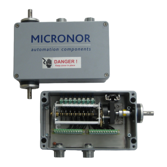
Product Overview Product Description MICRONOR MR221/MR222 series Heavy Duty Geared Limit Switches are designed for use in machine applications requiring the highest quality, industrial-grade CE approved limit switches. These heavy duty switches can be used in applications with side loads as high as 200 lbf (890 N) and axial loads up to 80 lbf (360 N). -
Page 6: Figure 1. Features Of The Mr221 One-Ended Geared Limit Switch
MICRONOR AG MR221/MR222 Series Geared Limit Switch User Guide Heavy Duty Easy Wiring To Phoenix Two ½” NPT Conduit NEMA/UL Type 1/4/4X COMBICON Wiring Hubs and Cover Plugs Enclosures: Strips. Also Supplied Are Pre-Installed Aluminum or Stainless With Pre-wired jumper. -
Page 7: Schematic Diagram
MICRONOR AG MR221/MR222 Series Geared Limit Switch User Guide Schematic Diagram Figure 3. MR221-MR222 Schematic Diagram Page 7 of 36... -
Page 8: Ordering Code
MICRONOR AG MR221/MR222 Series Geared Limit Switch User Guide Ordering Code MR2221 Alum MR222 Alum MR221-X SS MR222-X SS Page 8 of 36... -
Page 9: Initial Preparation
Warranty Information MICRONOR warrants this product to be free from defects in material and workmanship for a period of twelve (12) months from date of shipment. During the warranty period we will, at our option, either repair or replace any product that proves to be defective. - Page 10 MR221/MR222 Series Geared Limit Switch User Guide This warranty is in lieu of all other warranties, expressed or implied, including any implied warranty of merchantability of fitness for a particular use. MICRONOR or MICRONOR SENSORS shall not be liable for any indirect, special or consequent damages.
-
Page 11: Specifications
MICRONOR AG MR221/MR222 Series Geared Limit Switch User Guide Specifications Electrical, Mechanical and Environmental Parameter Specification Notes Enclosure Ratings UL/NEMA Type 1/4/4X Choice of die cast aluminum with powder coat + IP66 finish or stainless steel housing NOTE: IP rating applies only when unit installed, connected and torqued properly. -
Page 12: Position Output Option, Mr265 Loop-Powered Based
MICRONOR AG MR221/MR222 Series Geared Limit Switch User Guide -1 Position Output Option, MR265 Loop-Powered Based The MR22X-1 (MR265) option is a precision, 2-Wire, potentiometer-based, loop-powered 4-20mA output option. Parameter Specification Notes MR265 Potentiometer-based 4mA point programmable via Offset trimpot... -
Page 13: Test Summary
MICRONOR AG MR221/MR222 Series Geared Limit Switch User Guide Test Summary Parameter Specification Notes Temperature Test Standard Per UL 508, Section 43 Dielectric Voltage Standard Per UL 508, Section 49 Withstand Test Resistive Load Test Standard Per UL 508, Sections 45 (Overload) and 46... -
Page 14: Installation Guidelines
MICRONOR AG MR221/MR222 Series Geared Limit Switch User Guide Installation Guidelines Mounting The Enclosure Use appropriate hardware to mount limit switch enclosure. On the mounting screws, be sure to use caulking or other sealant appropriate for the operating environment and to ensure proper sealing. -
Page 15: Coupling To Customer Equipment's Shaft(S)
To order a coupling from most suppliers, the process is to select the coupling style (heavy duty/zero backlash) and the shaft dimensions (and any special features) of both sides. Designating Side A for the Micronor limit switch and Side B for the customer’s equipment (typically the drum or over speed sensor): •... -
Page 16: Wiring To The Limit Switch
MICRONOR AG MR221/MR222 Series Geared Limit Switch User Guide Wiring To The Limit Switch Important wiring notes • Use copper conductors rated 60°C or higher • Tighten terminal torque is 5-7 in-lbs • Unused conduit ports must be properly sealed to prevent moisture and water leakage into the unit. -
Page 17: Table 1. Wiring Table Template
MICRONOR AG MR221/MR222 Series Geared Limit Switch User Guide Table 1. Wiring Table Template Contact Switch Contact Cam Program Wire Color Signal Name Type (Input shaft degrees and Size or dial setting) Switch 1 Common Switch 1 Switch 1 Switch 2... -
Page 18: Programming The Cams
MR221/MR222 Series Geared Limit Switch User Guide Programming The Cams The Micronor Programmable Cam Switches are designed to be both versatile and easy to operate. However, initial planning is required for cams to be programmed to function as desired. Due to the design of the cam, switches cannot be engaged for more than 180°. -
Page 19: Connecting And Programming The 4-20Ma Position Output Options
MICRONOR AG MR221/MR222 Series Geared Limit Switch User Guide The following instructions may be used to program the start and stop times of each switch using the supplied PSN (black) cam programming tool: Turn external shaft to the desired START position via dial setting. Insert PSN key ith the numbered side away from the cam and the notched side towards the cam. -
Page 20: 4.5.1 Programming The -1 Mr265 4-20Ma Position Output Option
MICRONOR AG MR221/MR222 Series Geared Limit Switch User Guide 4.5.1 Programming the -1 MR265 4-20mA Position Output Option The MR22X-1 (MR265) 4-20mA Position Output Option is a 2-Wire or loop-power feedback option. That is, the loop is powered in series and provides the advantage that this feedback option can be powered remotely from the PLC location. -
Page 21: Figure 11. How To Set 4Ma/20Ma Points And Direction Of Mr265 Output
MICRONOR AG MR221/MR222 Series Geared Limit Switch User Guide Figure 11. How to set 4mA/20mA points and Direction of MR265 Output Page 21 of 36... -
Page 22: 4.5.2 Programming The -E Encoder-Based 4-20Ma Position Output Option
MICRONOR AG MR221/MR222 Series Geared Limit Switch User Guide 4.5.2 Programming the -E Encoder-based 4-20mA Position Output Option As shown in Figure 12 below, the MR221-MR222 Gear Limit Switch family also includes an option for 4-20mA position feedback via an integrated single-turn absolute encoder. The 4-20mA output is scaled over the full # of turns (gear ratio) of the ordered limit switch. -
Page 23: Maintenance And Service
Replaceable Parts The following replacement accessory part is available from Micronor: • PSN Cam Programming Key, Micronor P/N PSN (consult Section 4.4 for application) The following replacement component part is available from Micronor: • Microswitch, Micronor P/N 6099.22.846 (consult Section 5.2 for application) The following replacement gear lubricant is available from Etna-Bechem Lubricants Ltd: •... -
Page 24: Figure 14. How To Replace Microswitch
MICRONOR AG MR221/MR222 Series Geared Limit Switch User Guide To replace a microswitch, follow these steps while consulting Figure 14: Using a large slotted or Phillips screwdriver, remove cover by loosening the 4 mounting screws located on top. Using a slotted screwdriver, loosen (but do not remove) the two screws holding the rear mounting flange of the cam switch subassembly. -
Page 25: Lubricating Bevel Gear Junction (Mr222 Only)
MICRONOR AG MR221/MR222 Series Geared Limit Switch User Guide Lubricating Bevel Gear Junction (MR222 Only) Under normal conditions, it is not necessary to lubricate the bevel gears used on the MR222 models (see Figure 15, couples the main shaft to the cam switch shaft). However, if the inside becomes accidentally contaminated, it would become necessary to clean and lubricate gears. -
Page 26: Lubricating Cam Switch Gear Junction
MICRONOR AG MR221/MR222 Series Geared Limit Switch User Guide Lubricating Cam Switch Gear Junction Under normal conditions, it is not necessary to lubricate the cam gears (see Figure 15, couples from the gear reduction module to the main shaft of the cam switch subassembly). However, if the inside becomes accidentally contaminated, it would become necessary to clean and re- lubricate the gears. -
Page 27: Reference Drawings
MICRONOR AG MR221/MR222 Series Geared Limit Switch User Guide Reference Drawings The following pages provide reference drawings for each model: • Standard MR221 in Aluminum Housing, 925x.xx.xxx 2 pages • Standard MR221-E in Extended Aluminum Housing, 9350.03.373, 1 page • Standard MR222 in Aluminum Housing, 928x.xx.xxx, 2 pages •... - Page 28 MR221 (Die Cast Aluminum) 260 (10.236") Kontr. Gearded Limit Switch Single Shaft 309,6 (12.189") Frei. Zeichnungs Nr. MICRONOR AG 0-Series 20.10.06 MAZU CH - 8105 Regensdorf Prototype 20.06.06 MAZU T. 044 843 40 25 / Fax. 044 843 40 39...
- Page 29 23.10.2006 M.Z rcher MR221 (Die Cast Aluminum) Kontr. Gearded Limit Switch Single Shaft Frei. Zeichnungs Nr. MICRONOR AG 0-Series 20.10.06 MAZU CH - 8105 Regensdorf Prototype 20.06.06 MAZU T. 044 843 40 25 / Fax. 044 843 40 39 Modifikation...
- Page 30 26.04.2019 R. Schubert 1 : 2 Kontr. KWG360 L8 U25:1 ESA36 Analog Frei. Zeichnungs Nr. MICRONOR nderungen vorbehalten / subject to modification CH - 8105 Regensdorf 9350.03.373 T. 044 843 40 25 / Fax. 044 843 40 39 www.micronor.ch Aenderungen...
- Page 31 0,00 Kontr. 01.11.2006 12,70 - 0,05 (0.5") MR222 Serie Aluminium Frei. 01.11.2006 Zeichnungs Nr. MICRONOR AG 0-Series 20.10.06 MAZU 240(9.449") 928x.06.000 CH - 8105 Regensdorf Prototype 22.06.06 MAZU T. 044 843 40 25 / Fax. 044 843 40 39 Modifikation...
- Page 32 Objekt / Bezeichnung Gez. 20.10.2006 M.Z rcher Kontr. 01.11.2006 MR222 Serie Aluminium Frei. 01.11.2006 Zeichnungs Nr. MICRONOR AG 0-Series 20.10.06 MAZU 928x.06.000 CH - 8105 Regensdorf Prototype 22.06.06 MAZU T. 044 843 40 25 / Fax. 044 843 40 39 Modifikation Datum...
- Page 33 Objekt / Bezeichnung Gez. 23.10.2006 M.Zürcher Kontr. 01.11.2006 MR221 Serie Edelstahl Frei. 01.11.2006 Zeichnungs Nr. MICRONOR AG 0-Series 20.10.06 MAZU 926x.06.000 CH - 8105 Regensdorf 20.06.06 MAZU T. 044 843 40 25 / Fax. 044 843 40 39 Modifikation Datum Name...
- Page 34 Objekt / Bezeichnung Gez. 23.10.2006 M.Zürcher Kontr. 01.11.2006 MR221 Serie Edelstahl Frei. 01.11.2006 Zeichnungs Nr. MICRONOR AG 0-Series 20.10.06 MAZU 926x.06.000 CH - 8105 Regensdorf 20.06.06 MAZU T. 044 843 40 25 / Fax. 044 843 40 39 Modifikation Datum Name...
- Page 35 MR222 Series (Stainless Steel) - 0,05 Kontr. (0.5") Geared Limit Switch Double Shaft Frei. Zeichnungs Nr. 300 (11.811") MICRONOR AG 0-Series 20.10.06 MAZU CH - 8105 Regensdorf Prototype 22.06.06 MAZU T. 044 843 40 25 / Fax. 044 843 40 39 Modifikation...
- Page 36 28.09.2006 M.Z rcher MR222 Series (Stainless Steel) Kontr. Geared Limit Switch Double Shaft Frei. Zeichnungs Nr. MICRONOR AG 0-Series 20.10.06 MAZU CH - 8105 Regensdorf Prototype 22.06.06 MAZU T. 044 843 40 25 / Fax. 044 843 40 39 Modifikation...
Need help?
Do you have a question about the MR221 Series and is the answer not in the manual?
Questions and answers
What is the yellow colour coupling called which is in between shafts