Table of Contents
Advertisement
Quick Links
Advertisement
Table of Contents

Related Manuals for Pantech PG-1400


Summary of Contents for Pantech PG-1400
- Page 1 PG-1400 Service Manual PG-1400 PG-1400 Service Manual (GSM Cellular Phone) Pantech Co., Ltd., Korea September 5, 2005 Edition For Use by Authorized Service/Maintenance Personal Only Documents to Receive This Addendum: PG-1400 Maintenance/Repair/Operating Manual...
-
Page 2: Table Of Contents
PG-1400 Service Manual CONTENTS SECTION 1 INTRODUCTION ......................3 1.1 A GSM D ......3 NTRODUCTION OF IGITAL ELLULAR OBILE OMMUNICATION YSTEM 1.2 F ...................3 REQUENCY LLOCATION AND 1.3 I ........................4 AME AND 1.4 C .........................4 HARACTERISTICS SECTION 2 ELECTRICAL SPECIFICATIONS..................5 2.1 G ............................5... - Page 3 PG-1400 Service Manual 6.3 SIM CARD PART ……………………………………...………………………….………………… 34 6.3.1 SIM ………………………………………………………………………….…..…………. 34 ERROR 6.4 CHARGER PART………………….………………………………………………….…..………….. 35 6.4.1 C ……………….………………..……………………………….…………..…… 35 HARGING ERROR 6.5 RF PART…………….………………….……………………………………………………………… 37 6.5.1 T ……………….…….…………………………………………… …………………37 EST CONDITIONS 6.5.2 P ….…….……………………………………………………………….38 OWER UPPLY HECK POINT 6.5.3 P...
-
Page 4: Section 1 Introduction
PG-1400 Service Manual SECTION 1. Introduction 1.1 An Introduction of GSM Digital Cellular Mobile Communication System GSM (Global System for Mobile communication) concluded that digital technology working in the Time Division Multiple Access (TDMA) mode would provide the optimum solution for the future system. -
Page 5: Item Name And Use
PG-1400 Service Manual ** Fl(n)= frequency value of the carrier , Fu(n)= corresponding frequency value in upper band Item Name and Usage 1400, GSM digital cell phone, is supercompact, superlight mobile communication terminal for personal use. It has a 900MHz and 1800MHz frequency band and adopts GSM and DCS mode having excellent spectrum efficiency, economy, and portability. -
Page 6: Section 2 Electrical Specifications
PG-1400 Service Manual Section 2. Electrical Specifications 2.1 General E-GSM / DCS Band Mobile Transmit Frequency 880 MHz ~ 915 MHz/1710MHz ~ 1785MHz Mobile Receive Frequency 925 MHz ~ 960 MHz/1805MHz ~ 1880MHz The Number of Time Slot The Number of Channels... -
Page 7: Section 3 Operation
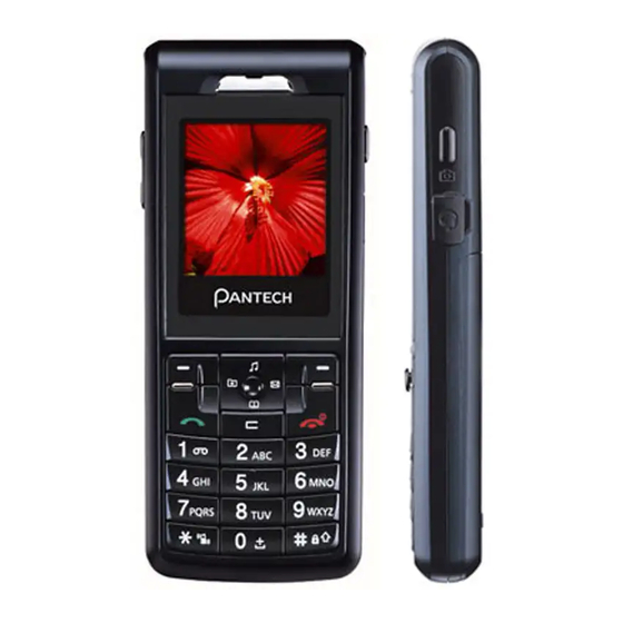
PG-1400 Service Manual Section 3 Operation 3.1 Name of each part Receiver Hall 1.5’ 65K CSTN (128*128 pixels) 5 Way Menu Joystick Key Soft Key 1 Soft Key 2 End/ Power on, off Clear Key Numeric Keypad MIC Hall Volume... -
Page 8: Display
PG-1400 Service Manual Display(LCD) Parameter Projected Actual(MAIN LCD) Display Color CSTN LCD with white LED back lighting 1.5” 65k colors Pixels : 128*128 pixels Character : (font size :12/14/16) 8characters x 10lines(max) Driver S6B33B9 (SAMSUNG Electronics.) Module Dimen. 36(W) x 48.2(H) x 5.2(D) Effective Area 27.26(W) x 34.07(H) -
Page 9: Section 4 Theory Of Operation
PG-1400 Service Manual Section 4. Theory of Operation 4.1 Logic Section 4.1.1 DC Distribution and Regulation Part Applying battery voltage and pressing “END” key on the key pad short-circuits “Ground” and “ PowerON”. AD6537B(U201) control that power manage regarding power on/off in handset Pressing POWERKEY on the key pad is active on the handset. - Page 10 PG-1400 Service Manual ☞ Configuration by Function of AD6527 1 Microprocessor Core AD6527 has a built-in ARM7 microprocessor core, including microprocessor interrupt controller, timer/counter, and DMA controller. And besides, 32bit data path is included, and up to 8Mbyte addressing is enabled and can be extended up to 16Mbyte. Although external clock should be provided to operate the microprocessor, this core uses 13MHz VCTCXO to provide clock.
-
Page 11: Memory Part
PG-1400 Service Manual 4 RF Interface This interfaces the RF part to control power amplifier, Tx LO buffer amplifier, VC-TCXO, and AGC-end on transmit/receive paths in the RF part. 1) Transmitter Interface: This sends Ramp signal to the RF part to control power amplifier. -
Page 12: Notification Part
PG-1400 Service Manual SRAM has a capacity of 32Mbit(4MByte) and stores system parameters, data buffer, and stack of each task in it. 3 Key Tone Generation All alert signals are generated by the DSP and output to the ABB audio output. -
Page 13: Radio Transceiver Section
4.2 Radio Transceiver Section Fig.4-1. RF Transceiver block diagram The PG-1400’s RF Transceiver, which is Aero II, is the industry's most integrated RF front end for multi-band GSM/GPRS digital cellular handsets and wireless data modems. The high-level of integration obtained through patented and proven design architectures, fine line CMOS process... -
Page 14: Dc Distribution And Regulation Part
4.2.3.1 An Overview of Receive section Fig.4-6. Receiver block diagram The PG-1400’s Aero II transceiver uses a digital low-IF receiver architecture that allows for the on-chip integration of the channel selection filters, eliminating the external RF image reject filters, and the IF SAW filter required in conventional superheterodyne architectures. -
Page 15: Receiver Part
PG-1400 Service Manual issues. However, since the Aero II transceiver has no requirement for BBIC support of complex dc offset compensation, it is able to interface to all of the industry leading baseband ICs. The receive (RX) section integrates four differentialinput low noise amplifiers (LNAs) supporting the E-GSM 900 (925–960 MHz), DCS 1800 (1805–1880 MHz) bands. -
Page 16: Transmit Section
PG-1400 Service Manual 4.2.4 Transmit Section 4.2.4.1 An Overview of Transmit Section Fig.4-8. Transmitter block diagram The transmit section consists of an I/Q baseband upconverter, an offset phase-locked loop (OPLL), and two 50 Ω output buffers that can drive an external power amplifier (PA). One output is for the E-GSM 900 (880–915 MHz) bands and one output is for the DCS 1800 (1710–1785 MHz) bands. -
Page 17: Vc-Tcxo(Voltage Controlled Temperature Compensated Crystal Oscillator)
PG-1400 Service Manual These passive components are adopted for PAM to operate in a stable output power. B. ASM (Antenna Switch Module / built in LPF) These filters pass through the signals of which frequency band of 880~915MHz, 1710MHz~1785MHz which is the transmit frequency of GSM, DCS system terminal, and it suppresses other images and spurious frequencies when the terminal transmits GMSK modulated frequencies. -
Page 18: Section 5 Alignment Procedure
PG-1400 Service Manual Section 5. Alignment Procedure 5.1 Recommended Test Equipment Model No. Description Maker Remark GSM Mobile Station 8960 Agilent Technologies Test Set 8593E Spectrum Analyzer Hewlett Packard TDS 340A Oscilloscope Tektronix FLUKE 87 Digital Multimeter Fluke E3630A DC Power Supply... -
Page 19: Section 6 Equipment Repair Procedure
PG-1400 Service Manual SECTION 6. Equipment Repair Procedure 6.1 No Power On with battery Applied. 6.1.1 Power CHECK 1. Check battery power : 3.5V~4.2V. Battery Pack Terminal 2. Check to see if C202.1 or C205 pin voltage is same with battery power : CP100... - Page 20 PG-1400 Service Manual CP100 3. Check to see if U408.5,6 and R221 pin is same with battery power : CP101 CP101 PANTECH...
- Page 21 PG-1400 Service Manual CP101 PANTECH...
- Page 22 PG-1400 Service Manual 4. Check to see if U201 and C224, C225, C227, C229, C232, C653, C654 pin is 2.8V_EXT, 2.8V_MEM, 1.8V_RTC, 1.8V_D, VMIC, VTCXO, VSIM, : CP102 CP102 CP102 PANTECH...
- Page 23 PG-1400 Service Manual 6. Check to see if U201.T14 pin becomes to 0V : CP103 Pressing “END” key to turn on equipment. CP103 7. Check to see if C101,C102,,, C105,C106,,C108,C111,C112, C113,C114, is 1.8V_D, 2.8V_EXT, VSIM, 1.8V_RTC : CP104 CP104 CP104...
- Page 24 PG-1400 Service Manual 8.Check to see if U509 and C132,C131 is 2.8V_MEM : CP105 CP105 CP105 PANTECH...
-
Page 25: Oscillation Check
PG-1400 Service Manual 6.1.2 Oscillation CHECK 1. Check to see if U101 No. E9 and C9 pin is oscillated(32.768KHz) : CP106 Check R132 and then replace X101 CP106 CP106 2. Check to see if U101.N10 pin Master Clock(13MHz). : CP107... -
Page 26: Keypad Led Not In Operation
PG-1400 Service Manual CP107 6.1.3 KEYPAD LED Not in Operation 1. Check to see R10, R11, R12, R13, R14, R15, R19, R20 : CP110 Replace the resistors. 2. Check R16 signal (control PWM) : CP111 3. Check Q1 CP110 CP111... -
Page 27: Lcd
PG-1400 Service Manual CP110 6.1.4 LCD Backlight Not in Operation (White) 1. Check to see if U101.A11 or R684,R685 pins are controlled GPIO (2.8V): CP112 CP112 CP112 PANTECH... -
Page 28: Audio Part ( Earpiece, Hands-Free Earphone, Microphone, Hands-Free Mic )
PG-1400 Service Manual 6.2 Audio Part ( Earpiece, Hands-free Earphone, Microphone, Hands-free Mic ) 6.2.1 No receiving tone heard ( Ear-piece ) 1. BEEP TONE: Check U201.J15 and K15(C208,C209,) pins (Ear Signal) for waveform : CP113 Replace U201. 2.VOICE,BELL TONE : Check U301.17, 18 and C675,C417 pins for waveform. : CP114 Replace U301. -
Page 29: N Oreceiving Tone Heard (Hands Free Earphone )
PG-1400 Service Manual CP114 6.2.2 No Receivng tone heard ( Hands-free Earphone ) 1. Check to see if U101.J16 (R619) is around 0V: Check to see J510 : CP115 Set to HP8922M to connect a call and then set to 1kHz. -
Page 30: Sidetone Not Transmitted (Earpiece )
PG-1400 Service Manual 6.2.3 Side Tone Not transmitted ( Ear-piece ) Repeat 6-2-1 No receiving tone heard.( Ear-piece ) 1. Check to see if Mic + pin is around 1.5V : CP117 Check that R677, C210, C211, R206 and R205 is cold solder, broken, short to the other PCB pattern or not If you find out any defective part, you replace it. -
Page 31: Sidetone Not Transmitted (Hands Free Mic )
PG-1400 Service Manual 6.2.4 Side Tone Not transmitted ( Hands-free Mic. ) Repeat 6-2-2 No receiving tone heard.( Hands-free Earphone ). 1. Check to see if R218 pin is 2.5V : CP119 Check that C222 is cold solder,broken,short to the other PCB pattern or not. -
Page 32: Hook Switch Not Working
PG-1400 Service Manual 6.2.5 Hook Switch not working 1. Check to see if Q2.1 pin is 2.4V : CP120 2. Check to see if Q2.1 pin is 0V during pressing Hook Switch : CP120 3. Check to see if U2.3 pin is around 0V, when you press Hook Switch : CP120... -
Page 33: Melody Not Ringing
PG-1400 Service Manual 6.2.6 Melody not ringing 1. Check to see if C303, TC301 is Vbat : CP121 2. Check to see if C302, TC300 is 2.8 V : CP122 3. Check U301.12, 13, 14 pin for waveform: CP123 Check that C306, R301,R302, C307and R303 cold solder, broken, short to the other... -
Page 34: Vibrator Not Working
PG-1400 Service Manual 6.2.7 Vibrator not working 1. Check to see if R683 pin is 2.8V : CP124 Check to see R683cold solder, broken, short to the other PCB pattern or not If you find out any defect, you replace it 2.Check to see Vibrator... -
Page 35: Sim Card Part
PG-1400 Service Manual 6.3 SIM card part 6.3.1 SIM error Check to see if J508.1 pin is around 2.85V : CP126 Check to see C658 pin cold solder, broken, short to the other PCB pattern or not : If you find out any defect, you replace it 2.Check to see J508.2, 3, 6(R116,R117,R118) for wave form : CP127... -
Page 36: Charger Part
PG-1400 Service Manual CP126 6.4 Charger part 6.4.1 Charging error Insert adaptor into I/O jack. Check to see if C133 pin or U524.4 is 5.2V : CP128 Check to see CN1.23, 24(I/O connector) pin and U524 cold solder, broken, short to the... - Page 37 PG-1400 Service Manual CP128 CP129 CP129 PANTECH...
-
Page 38: Rf Part
PG-1400 Service Manual 6.5 RF Part 6.5.1 Test conditions 1. Test condition 1 : VBAT = 3.8V during all tests 2. Test condition 2 : Traffic channel :GSM900 Band Tx mode Ch62 Power Level : 13 3. Test condition 3 : Traffic channel : DCS Band... -
Page 39: Power Supply Check Point
PG-1400 Service Manual Step 2-1 Step 2-2 Fig.6-1 Power Supply Schematic U513 Regulator Step 2-2 Step 2-1 Fig.6-2 U513 Regulator Power Supply PCB Layout PANTECH... - Page 40 PG-1400 Service Manual Step 2-3 Fig.6-3 U512 PAM’s Power Check Point Step 2-3 Fig.6-4 U512 PAM’s PCB Layout PANTECH...
-
Page 41: Power Amplifier Module
PG-1400 Service Manual 6.5.3 Power Amplifier Module Step Test point Typical Value Condition Checking Point U512 Logic High 2, 3 Check route connection : PAM_ENABLE Pin#18 Logic High Check this pin 1, When Logic High, then U512 DCS Mode. While Logic Low , GSM900 Pin#1 mode is operating. -
Page 42: C - Tcxo
PG-1400 Service Manual STEP 3-1 STEP 3-2 Fig.6-6. U512 PAM ENABLE and DCSSEL Test Point on the PCB Layout 6.5.4 VC-TCXO Test Step Typical Value Condition Reaction to Abnormality point U503 0.5V ~ 2.5V 1,2,3,4,5,6 Check route connection : AFC... - Page 43 PG-1400 Service Manual STEP 4-2 STEP 4-1 Fig.6-7. U503 VCTCXO Check Point Circuit STEP 4-2 STEP 4-1 Fig.6-8. U503 VCTCXO Check Point on the PCB Layout 6.5.5 Antenna Switch Module Typical Step Test point Condition Check point Value U548 When Pin#4 is Logic High and Pin#8 is 2.8V...
-
Page 44: Antenna Switch Module
PG-1400 Service Manual STEP 5-3 STEP 5-1 STEP 5-2 Fig. 6-9 U548 Antenna Switch Module Circuit STEP 5-2 STEP 5-1 Fig. 6-10 U548 Antenna Switch Module PCB Layout PANTECH... - Page 45 PG-1400 Service Manual 6.6. FM Radio Module 6.6.1 Check point power part in the FM radio mode CP1 : It is high if system is turned on 6.6.2 Check point communication part in the FM radio mode (Initialization, Set Frequency) CP2 : 3.15MHz clock is generated for initialization of FM radio IC or setting frequency.
- Page 46 PG-1400 Service Manual 6.6.3 Check output part in the FM radio mode CP 4: FM radio output signal PANTECH...
- Page 47 PG-1400 Service Manual PANTECH...
Need help?
Do you have a question about the PG-1400 and is the answer not in the manual?
Questions and answers