Table of Contents
Advertisement
Quick Links
Advertisement
Table of Contents

Related Manuals for Flexit ProNordic CS2500


Summary of Contents for Flexit ProNordic CS2500
- Page 1 118076EN-02 2022-06 CS2500 ART.NO. 118044 USER MANUAL ProNordic...
-
Page 2: Table Of Contents
C S 2 5 0 0 Contents Introduction ............................4 1.1. Document description .......................4 1.2. Highlighted boxes ........................4 1.3. System overview ..........................5 1.3.1. System structure ......................5 1.3.2. Ventilation unit’s switching space .................6 1.3.3. Ventilation unit control cabinet ..................8 Quick guide ............................10 2.1. - Page 3 Summer/Winter compensation ......................31 8.1. Adjustment of fan setpoint in case of high/low outdoor air temperatures ...... 31 8.2. Parameter settings for fan compensation ................31 8.3. Adjustment of temperature setpoint in case of high/low outdoor air temperatures ..31 8.4.
-
Page 4: Introduction
C S 2 5 0 0 Introduction 1.1. Document description This document describes the main functions of the want to make basic settings to start the ventilation select the relevant section in the document. All electrical connections must be made by an expert. 1.2. -
Page 5: System Overview
1.3. System overview 1.3.1. System structure on the outside of the ventilation unit Terminal blocks Regulator - the ventilation unit’s general control Fuse for automatic control and fans (not electric heating coil) Terminal board - a circuit board with terminal Modbus extender - a communication card that accessories regulator via data communication... -
Page 6: Ventilation Unit's Switching Space
C S 2 5 0 0 1.3.2. Ventilation unit’s switching space Power supply board Modbus extender electric heating coil) and control cabinet. There is also a A communication card that connects the ventilation terminal block for the return water sensor. Component Function Terminal block for accessories... - Page 7 Block 3 Block no. Function Type 24VAC AO 0-10V (EV heating EB1 control signal) Alternative earth (F10 Overheating thermostat EB1 signal) Alternative (Not used) EV2 (Potential-free contact) EV2 (Potential-free contact) L1 Out 230V L1 Out 230V C S 2 5 0 0...
-
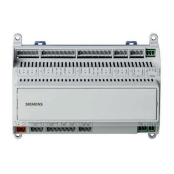
Page 8: Ventilation Unit Control Cabinet
C S 2 5 0 0 1.3.3. Ventilation unit control cabinet Regulator installed under the cover. POL648.10 INFO! The ProTouch panel is not mentioned in further detail in this manual. Please see the separate manual for the panel. - Page 9 Terminal board Block 10 Block no. Function Type Alarm NO Cooling C contact) 1 2 3 4 5 6 7 8 9 10 11 12 13 14 15 16 17 18 19 20 21 22 23 24 25 26 27 28 29 30 31 32 33 34 35 36 37 38 39 40 41 42 43 44 Cooling NO contact) L1 Out...
-
Page 10: Quick Guide
C S 2 5 0 0 Quick guide 2.1. HMI ProPanel Info button Press to enter the main menu • • • Nighttime cooling or Night heating/nighttime cooling. • • Display Shows information Dial • menus or to change values •... -
Page 11: Login
2.2.3. Login 2.2.4. Set time/time channels Start page > Quick menu > SetUp > Date/ Time Input 2.2.5. Set the calendar and timing program Start page > Quick menu > SetUp > in the manual to describe the login level before the Timeswitch program General This section describes functions and settings for the... -
Page 12: Week Schedule
C S 2 5 0 0 2.2.6. Week schedule 2.2.7. Day schedule Parameter Value Function Parameter Value Function Present value Switch-over according to Present value --- Switch-over according to the schedule Shows current command when latest time that can be entered -Passive -Active -Tu-Fr... -
Page 13: Calendar (Exceptions And Stop)
2.2.8. Calendar (exceptions and stop) Calendar exceptions Calendar stop Parameter: Start page > Quick menu > SetUp > Timeswitch program > Calendar execption Start page > Quick menu > SetUp > before 23 December. Parameter Value Function Current value Shows whether a calendar time is -Passive - No calendar time activated -Active... -
Page 14: Adjust Setpoints For Speeds And Temperatures
C S 2 5 0 0 2.3. Adjust setpoints for speeds and RESTART temperatures Start page > Quick menu > Settings > Setpoints/Settings Parameter Function Start page > Quick menu > Settings > Setpoints/Settings All settings Parameter Function 2.6. The standard setting for the unit is m 2.4. -
Page 15: Backup And Program Updates
Backup and program updates Start page > Main menu > System objects > Save/load > Ready 3.2. Procedure: Start page > Main menu > System objects Start page > Main menu > System objects > Save/Load > Sett.load > Ext. m > Execute Save/Load 3.1. -
Page 16: General Functions
C S 2 5 0 0 General functions Operating modes - Changes Start page > Main Menu > Unit > Operating mode > Manual operation Manual operation Eco.St1 Comf.St1 Eco.St2 Comf.St2 Eco.St3 Comf.St3... - Page 17 This section is, therefore, intended more as general information. • • • 5.1. • • Execute NB. The ventilation unit is supplied fully configured and does not normally need to be changed. RESTART Parameter Value Function General Expansion modules No be set to On.
- Page 18 C S 2 5 0 0 Parameter Value Function Filter alarm Combined Filter alarm ana logue Emergency stop Alarm ackn input are reset. Su/Wi input Summer-winter mode. TSP function TSP steps Comf1. Econ2, Comf1, Comf2. Econ2, Econ3, Comf1, Comf2, Comf3. Ext control input None trol, etc.
- Page 19 Parameter Value Function Extract air tmp Supply tmp sensor Outs air tmp sensor Hrec supply air Functions Exhaust air Damper Combined Outside Ziehl-Abegg Fan control Direct mode DirectVar Pressure Flow C S 2 5 0 0...
- Page 20 C S 2 5 0 0 Parameter Value Function Tmp control mode Rm casc. Room Hrec damper Active increases to 60%, the fan decreases to 40%. Heat recovery Waterheating No Electrical heating No electric heating register available. Analog Water Heating...
- Page 21 Parameter Value Function El Heating 2 Analog Cooling Cooling 2 Fire damper FollowUnit 2+FolwUn 3+FolwUn 4+FolwUn Firefan Fire fan control deactivated. Fire fan control activated. External set point Volt QAA27 BSG21 Not done Done Restart required C S 2 5 0 0...
- Page 22 C S 2 5 0 0 5.2. • • NB. The ventilation unit is supplied fully configured and does not normally need to be changed. Start Start page > Log in Preconditions: restart of the regulator. Parameter Value Function Free cooling None Nighttime cooling deactivated.
- Page 23 Parameter Value Function Fan steps freq conv Flow display The function is not available. /hour. Fan steps type or Dir.fro. Fan alarm No alarm. Combined Fan fdbk No return. Combined Fan deviation alarm No monitoring Fan comp room tmp Fan comp air qual C S 2 5 0 0...
- Page 24 C S 2 5 0 0 Parameter Value Function Ext. Fan setpoint Function deactivated Ext. SP funct. Relative Supply Fan Absolute Ext stpt funct.Exh Relative Absolute Fan comp outs tmp No Fan htg / clg Tmp stpt selection +/- 1/2Dz Clg-Dz Room temp.
- Page 25 Parameter Value Function Su/Wi comp tmp Hrec frost protect Detector water sensor. PressSnsr Pres+Dtctr Hrec (pump) cmd Yes+Kick Heat recovery No alarm. alarm Alarm Fdbk Both Hrec clg recovery Aux binary inputs Alarm Smoke alarm Smoke det. Fire Fan contr. Aux tmp sensor Aux TSP output AdjDiscrg...
- Page 26 C S 2 5 0 0 Parameter Value Function Done Not Done Restart required! Air quality damper comp. Function deactivated Function activated Cold recovery. mixing Function activated Frost guard, heating Frost guard for water heating Sensor Guard Sens+Guard Pump water heat Pump alarm water heating Alarm...
- Page 27 Parameter Value Function Cooling pump Yes+Kick Cooling pump alarm Alarm Fdbk Both HP Defrosting Function deactivated Function activated Fire damper reset Closed Comb. Closed.inv C S 2 5 0 0...
- Page 28 C S 2 5 0 0 5.3. NB. The ventilation unit is supplied fully configured and does not normally need to be changed. for the current sensor conversion (e.g. Ni1000, Pt1000, NB. The inputs and outputs in the expansion modules can be used if Positions in regulator and expansion modules the module has been activated in •...
-
Page 29: Cooling
Cooling 6.3. To activate the circulation pump (liquid cooling only) DX cooling one step or liquid Parameter Function machine). Cooling control in accordance with following Yes+Kick guidance. 6.1. Installation 6.4. Blocking for outdoor air temperature 1 2 3 4 5 6 7 8 9 9 10 10 11 12 13 14 15 16 17 18 19 20 14 15... -
Page 30: Cooling Limitation As Function Of Fan Speed (Dx Cooling Only)
C S 2 5 0 0 Temperature regulation 6.6. Cooling limitation as function of fan speed (DX cooling only) 7.1. Extract cascade Start page > Main menu > Unit > Temperature regulation > Cooling > Max. signal fan step (Extract air casc). To do this, go into the following menu. Parameter Function Parameter... -
Page 31: Summer/Winter Compensation
Summer/Winter compensation 8.3. Adjustment of temperature setpoint in case of high/low outdoor air Summer compensation: temperatures Parameter Function Winter compensation: Function deactivated Function activated 8.1. Adjustment of fan setpoint in case of high/low outdoor air temperatures RESTART Parameter Function 8.4. Parameter settings for temperature Function deactivated compensation... -
Page 32: Settings Switch Between Summer/Winter Operation
C S 2 5 0 0 8.5. Settings switch between summer/ winter operation 1 2 3 4 5 6 7 8 9 10 11 12 13 14 15 16 17 18 19 20 21 22 23 24 25 26 27 28 29 30 31 32 33 34 35 36 37 38 39 40 41 42 43 44 34 35 32,34,35 Block no. -
Page 33: Switch Between Summer/Winter Via Date/Outdoor Air Temperature
8.7. Switch between summer/winter via 8.8. Free cooling date/outdoor air temperature Night cooling works so that the unit can start and run at Start page > Main menu > Global functions > State Parameter Function Status status Parameter Function SuWi setting None No limitations Free cooling deactivated... -
Page 34: Support Operation
C S 2 5 0 0 8.9. Support operation 8.9.2. Start page > Main menu > Unit > from overheating or overcooling. This is regulated via a Operating mode > Tmp start Parameter Function Start stpt cooling Start cooling Cooling set point cooling is activated Start stpt heat... -
Page 35: Temperature Test For Free Cooling Operation
8.10. Temperature test for free cooling >EXAMPLE NIGHTTIME COOLING operation The function is used when room sensors are whether the unit should continue in night cooling / 17 degrees. activate the function. Execute RESTART Start page > Main Menu > Unit > Operating mode >... -
Page 36: Fan Regulation
C S 2 5 0 0 Fan regulation 9.2. Pressure control sensors must be mounted and connected to the unit. 9.1. Select method of regulation 9.1.1. Selection fan regulation method using other makes, these should be connected to Block All fan regulation functions are selected under the menu P12, see table. -
Page 37: External Setpoint Fan
9.3. External setpoint fan Extract air press Parameter Function 500Pa sure sensor. 1 2 3 4 5 6 7 8 9 10 11 12 13 14 15 16 17 18 19 20 21 22 23 24 25 26 27 28 29 30 31 32 33 34 35 36 37 38 39 40 41 42 43 44 43 44 Block Setpoint adjustment of pressure. -
Page 38: Parameter Settings For Comp
C S 2 5 0 0 Execute RESTART Ext stpt funct.Exh 9.3.1. Parameter settings for Comp. Parameter Function Relative Start page > Quick menu > Setup > Setpoints/Settings > All settings > Fan control > Supply fan/Extract fan Parameter Function Absolute Act supply stpt Act extract stpt... -
Page 39: External Fan Control Via Digital Inputs
9.4. External fan control via digital inputs 1 2 3 4 5 6 7 8 9 10 11 12 13 14 15 16 17 18 19 20 21 22 23 24 25 26 27 28 29 30 31 32 33 34 35 36 37 38 39 40 41 42 43 44 23 24 25 26 23, 24 25, 26... -
Page 40: Connection Of External Equipment
C S 2 5 0 0 10. Connection of external 10.1. Fire damper Execute RESTART To activate the function. 1 2 3 4 5 6 7 8 9 9 10 10 11 12 13 14 15 16 17 18 19 20 21 22 23 24 25 26 27 28 29 30 31 32 33 34 35 36 37 38 39 40 41 42 43 44 4 35 9, 10... - Page 41 Start page > Main menu > Unit > Damper control > Fire damper cmd Parameter Value Function Operation Feedback opened 1 / 2 / 3 /4 Feedback closed combinations State Closed Closed Mode Test Test mode. Alarm Alarm mode Opening time 1…600 [s] Closing time 1…600 [s]...
- Page 42 C S 2 5 0 0 Otherwise an alarm is triggered for lack of movement. Otherwise an alarm is triggered for lack of movement. Automatic testing can be carried out at a certain time > EXAMPLE TEST INTERVAL: 47 h No automatic test is carried out.
-
Page 43: Fire/Smoke Detector
10.2. Fire/smoke detector 1 2 3 4 5 6 7 8 9 10 11 12 13 14 15 16 17 18 19 20 21 22 23 24 25 26 27 28 29 30 31 32 33 34 35 36 37 38 39 40 41 42 43 44 Parameter Function Function... -
Page 44: Air Quality
C S 2 5 0 0 10.3. Air quality 1 2 3 4 5 6 7 8 9 10 11 12 13 14 15 16 17 18 19 20 21 22 23 24 25 26 27 28 29 30 31 32 33 34 35 36 37 38 39 40 41 42 43 44 8 29 30 29,30 Block no. -
Page 45: Aux Damper
10.4. AUX Damper 10.5. AUX operating mode indicator default, this is the buzzer alarm, but other functions can be selected. See table. Parameter Value Function Aux Analog outp generates a 0-10V signal, Start page > Main menu > Unit > Auxiliary >... -
Page 46: Internet
C S 2 5 0 0 11. Internet Start page > Main menu > and note Current IP. Start page > Main menu > Communication following information. Parameter Function Active Username: from the network. Password: Passive regulator. Start page > Main menu > Restart RESTART... -
Page 47: Modbus Tcp/Ip & Rs485
12. ModBus TCP/IP & RS485 Parameter Function Slave address or RS485 (RTU) as a standard function in the regulator. +RS485:1 Parameter Function +RS485:2 Start page > Main menu > Baud rate Parity Stop bit Delay Parameter Function Response Active timeout from the network. -
Page 48: Dx Heating/Cooling
C S 2 5 0 0 13. DX heating/cooling RESTART heating and cooling, which is connected to a ducted For the function to operate, I/O module SP90 Parameter Function manual If you wish to use the internal electric-powered Yes+Kick in the manual supplied with the coils. 13.1. - Page 49 Parameter Function Standalone Sequence Defrost Parameter Function Block P12-35 Select ´D4´ This will connect block P12-35 on the A2 Parameter Function Selection of coil function for both heating and cooling One coil for both heating and cooling 1Valve Coil with combined valve for Start page >...
-
Page 50: Installation
C S 2 5 0 0 13.2. Installation 1 2 3 4 5 6 7 8 9 10 11 12 13 14 15 16 17 18 19 20 21 22 23 24 25 26 27 28 29 30 31 32 33 34 35 36 37 38 39 40 41 42 43 44 4 35 32,35 Parameter... -
Page 51: Combi Battery
14. Combi battery guard are connected as instructed below. 14.1. Installation 1 2 3 4 5 6 7 8 9 10 11 12 13 14 15 16 17 18 19 20 12 13 14 15 21 22 23 24 25 26 27 28 29 30 31 32 33 34 35 36 37 38 39 40 41 42 43 44 31 32 33 1, 2 12, 13, 14, 15... - Page 52 C S 2 5 0 0 14.2. To set the valve switching between heating and cooling described below. Parameter Function Water Start page > Main menu > Unit > Auxiliary > Op mode outp select Parameter Function Water Parameter Function Summer and cooling) activated when the unit enters Winter...
- Page 53 C S 2 5 0 0...
- Page 54 C S 2 5 0 0...
- Page 55 C S 2 5 0 0...
- Page 56 Flexit AS, Televeien 15, N-1870 Ørje www.flexit.no...
Need help?
Do you have a question about the ProNordic CS2500 and is the answer not in the manual?
Questions and answers