Advertisement
Quick Links
I-UPS
Modbus TCP and Serial
SCADA INTERFACE
OPTION 21Q / 21S
INSTRUCTIONS
This manual is valid for I-UPS equipped RS-485 serial port.
Option 21Q - TCP/IP and RS-232 serial provided on 383S Communication Board
Option 21S – RS-232 serial provided via RS-485 to RS-232 converter.
ECN/DATE
CPN 147722
106 BRADROCK DRIVE
DES PLAINES, IL. 60018-1967
(847) 299-1188
FAX: (847) 299-3061
ISSUE DATE: ECN 23295 11/2022
INSTRUCTION DRAWING NUMBER:
LOPT21QS-I-UPS-01
P25-
Advertisement

Subscribe to Our Youtube Channel
Related Manuals for La Marche 21Q

Summary of Contents for La Marche 21Q
- Page 1 OPTION 21Q / 21S INSTRUCTIONS This manual is valid for I-UPS equipped RS-485 serial port. Option 21Q - TCP/IP and RS-232 serial provided on 383S Communication Board Option 21S – RS-232 serial provided via RS-485 to RS-232 converter. ECN/DATE CPN 147722 106 BRADROCK DRIVE DES PLAINES, IL.
-
Page 2: Default Settings
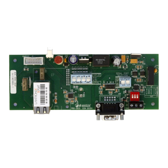
Default Settings The LaMarche Communications Card is shipped with the following settings. Settings CANNOT be changed. Port: RS485 (RS-232 port and TCP/IP communication can be selected). Baud Rate: 115200 Data Bits: 8 Stop Bits: 1 Parity: None Address: 0 Board Configuration The communications card may be configured for RS232, TCP communications. - Page 3 RS232 & RS485 Serial Applications For RS-232 – connect to the S2A-383S-20D1 PCB. Make sure the dip switch SW4 is set to RS-232. For RS-485 communication, connect directly to the RS-485 port in the unit – positions A (D-) and B (D+). Disconnect the serial converter wired to this port.
- Page 4 To assign the desire IP settings press the Assign IP button on the Toolbar. This will bring up the following screen: The Device Identification is located on the device itself as described in the dialog text above. An example of the Lantronix device is pictured below. Page 4 of 12...
- Page 5 In the example above the Device Identification would be 00-20-4A-C4-DF-E8. Note this is unique to each device. After entering the ID press Next. This dialog presents a choice between assigning an IP dynamically which would allow the device to operate on a network with a DHCP server however it is recommended that a specific IP address be assigned so it can be referenced directly on a SCADA Network.
- Page 6 Enter your desired IP settings and press Next. Pressing Assign will start the process of programming the device to the new IP Settings. A progress bar and Status will appear indicating a successful operation as shown below: Page 6 of 12...
-
Page 7: Parity - None
Pressing Finish will complete the IP setting change process. The DeviceInstaller Application can now be closed. LaMarche Modbus Implementation MODBUS - RTU, BAUD RATE - 115200, PARITY - NONE, SLAVE ID - 0, STOP BIT - 1 BIT Sr No. PARAMETER DETAIL Modbus Register... - Page 8 M_BATT_ test _RESULTS 30009 unsigned int M_CONFIG_ACKNOWLEDGEMENT 30010 unsigned int 0x1111/ M_PHASE_SHIFT 30011 unsigned int 0x1357 M_BATT DISCHARGE ELAPSED TIME 30012 unsigned int M_REMOVED AH 30013 Minutes unsigned int M_BATTERY SOC 30014 unsigned int M_AH RATING 30015 unsigned int M_VERSION 30016 unsigned int 30017...
- Page 9 M_SYSTEM_STATUS[0] 30050 unsigned int M_SYSTEM_STATUS[1] 30051 unsigned int M_SYSTEM_STATUS[2] 30052 unsigned int M_BYPASS_STATUS[0] 30053 unsigned int 30054 unsigned int P_BATTERY_TEMP P_AMBIENT_TEMP 30055 unsigned int P_COMMUNICATION_STATUS 30056 unsigned int 30057 unsigned int STATIC SWITCH CARD S_INVERTER_VOLTAGE, 30058 S_INVERTER_LOAD, unsigned int 30059 S_INVERTER_FREQUENCY, unsigned int 30060...
- Page 10 M_CHARGER_STATUS[0] ChargerFlags.Charger_off_SHORT_CKT Bit 8 ChargerFlags.Charger_off_CV_HIGH Bit 7 ChargerFlags.Charger_off_MAINS_FAULT Bit 6 ChargerFlags.Charger_off_OVERHEAT Bit 5 ChargerFlags.MAINS_ABSENT Bit 4 ChargerFlags.MAINS_1_PHASE_ABSENT Bit 3 ChargerFlags.ALARM_CHARGER_OVERHEAT Bit 2 M_CHARGER_STATUS[1] ChargerFlags.CHARGER_ON_STATUS Bit 1 ChargerFlags.FREQ_OUT Bit 8 ChargerFlags.MAINS_HIGH_PH3 Bit 7 ChargerFlags.MAINS_HIGH_PH2 Bit 6 ChargerFlags.MAINS_HIGH_PH1 Bit 5 ChargerFlags.MAINS_LOW_PH3 Bit 4 ChargerFlags.MAINS_LOW_PH2 Bit 3 ChargerFlags.MAINS_LOW_PH1...
- Page 11 Flags2.BypassVoltageRefOK Bit 8 Flags2.InvCurrentRefOK Bit 7 Flags2.InvFBVoltageRefOK Bit 6 Flags2.MainsVoltageRefOK Bit 5 Flags2.MainsCurrentRefOK Bit 4 Flags2.LoadCurrentRefOK Bit 3 INVERTER NTC OPEN Bit 2 M_SYSTEM_STATUS[1] Flags2.DC_AUX_SWITCH Bit 1 flage2.Flag reset done Bit 8 Flags2.INPUT_AUX_SWITCH Bit 7 Flags2.DC_contractor_ON Bit 6 Flags2.UPPER_INV_FAN_FAIL Bit 5 Flags2.LOWER_INV_FAN_FAIL Bit 4 Flags2.FUSE_FAIL...
- Page 12 S_INVERTER_STATUS[0] Flags2.INVERTER_FAULT InverterFlags.Inv_off_OVERLOAD Bit 8 Flags2.INVERTER_FAULT_FAST_SENSE Bit 7 Flags2.INVERTER_FREQ_OUT Bit 6 Flags2.INVERTER_VOLTAGE_HIGH Bit 5 Flags2.INVERTER_VOLTAGE_LOW Bit 4 Flags2.INVERTER_ABSENT Bit 3 Flags2.system in inverter Bit 2 S_SYSTEM_STATUS[0] Flags2.OPCurrentRefOK Bit 1 Flags2.OPVoltageRefOK Bit 8 Flags2.BypassCurrentRefOK Bit 7 Flags2.BypassVoltageRefOK Bit 6 Flags2.InvFBVoltageRefOK Bit 5 TransferTestResult[2] Bit 4 Bit 3...
Need help?
Do you have a question about the 21Q and is the answer not in the manual?
Questions and answers