Advertisement
Quick Links
DL-ISO
High Voltage Optically Isolated Probes
© 2022 Teledyne LeCroy, Inc.
All rights reserved.
935237-00 Rev A
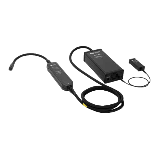
Probe Assembly and Connection
1. Connect the supplied AC to DC adapter to the DC inlet
port on the control module, then connect to AC power.
CAUTION: Use only the adapter shipped with the
probe. The probe must be powered from a supply
that provides appropriately isolated and floating
output voltage (i.e., no Earth connection).
2. Connect the probe to the oscilloscope through the
ProBus interface.
3. Insert the probe tip into the
connector on the probe head.
Be sure the arrows on the
connectors align.
4. Connect the tip to a de-energized
circuit.
Connecting Tips
MMCX tips can be used for low-voltage signals up to their
rated amplitude. Seat MMCX tips directly into MMCX
connectors on the circuit.
To connect MMCX tips to square-pin
headers, attach the MMCX to square-
pin adapter to the tip, then press it
onto the pins.
Note: The order of the three pins
in the adapter is reference-signal-
reference.
HV square-pin tips connect to
differential +ve and -ve signals on
circuits. On the tip, you will see a
red + and a white - indicating which
side connects to signal and which to
reference.
Most tip accessories have a red and a black interface.
Red connects to signal and black connects to reference.
The DL-ISO probes enable the highest confidence in GaN and
SiC device characterization with highest accuracy, best signal
fidelity and comprehensive connectivity for testing servers,
motherboards, mobiles, lighting and building automation,
residential inverters, UPS, switch-mode power supplies and
motors. With up to 1 GHz bandwidth, 2500 V differential
input range and 60 kV common mode range, they provide an
industry-leading 1.5% system accuracy when used with
12-bit High Definition Oscilloscopes.
For the complete manual, visit:
teledynelecroy.com/probes/high-voltage-optically-isolated-probes
Compatibility
Use only with compatible Teledyne LeCroy instruments
running Windows 10 and 64-bit MAUI firmware v.10.1.x.x or
higher. For a current list of compatible instruments, visit:
teledynelecroy.com/probes/high-voltage-optically-isolated-probes
Standard Parts
DL-ISO Probe
Optical probe head and control module connected by
integrated fiber-optic cable, transmits appropriately
attenuated voltage to the oscilloscope input.
External AC to DC Adapter
Provides appropriately isolated and floating output voltage to
power the probe. From CUI, Inc., Part Number: SMI36-24.
Tripod Probe Mount
Secures probe above circuit in a stationary test setup.
Soft Storage Case
Soft case with custom foam insert.
Tips
At least one attenuating tip is required for operation.
MMCX Tips
High-quality coaxial attenuating tips reject unwanted noise
while terminating into standard MMCX connectors.
DL-ISO-2V-TIP
2 Vpp input dynamic range
50 V (DC+Peak AC) max. non-destruct*
DL-ISO-10V-TIP
10 Vpp input dynamic range
100 V (DC+Peak AC) max. non-destruct*
DL-ISO-40V-TIP
40 Vpp input dynamic range
250 V (DC+Peak AC) max. non-destruct*
DL-ISO-200V-TIP
200 Vpp input dynamic range
300 V (DC+Peak AC) max. non-destruct*
High Voltage Square Pin Tips
HV safe attenuating tips connect to square-pin headers.
DL-ISO-1000V-Tip
1000 Vpp input dynamic range
1250 V (DC+Peak AC) max. non-destruct*
DL-ISO-2500V-Tip
2500 Vpp input dynamic range
3300 V (DC+Peak AC) max. non-destruct*
Refer to the tip derating graph below for values to 1 GHz maximum.
*
Operation
When the probe is connected to an oscilloscope, the
probe dialog is displayed behind the input channel setup
dialog (Cn). It shows the connected probe's attributes.
Use the buttons for Precision Gain Calibration and Auto Zero
to initiate those procedures.
Calibration Status indicator shows whether the Gain
Calibration in use is valid (green checkmark Pass) or is invalid
and should be repeated (red X Fail).
Warming Up indicator shows whether probe is still in warm-
up phase or ready for use.
Use the External Power On/Off checkbox to turn off power
from the AC to DC adapter without physically disconnecting it
from the probe.
Non-destruct Input Voltage (tip derating)
Tip Accessories
WARNING: The probe, tips and accessories are
classified No Rated Measurement Category per
IEC/EN 61010-2-030:2021 definitions. No Rated
Measurement Category applies to circuits not
directly connected to the mains supply. The
measurement terminals of the probe as well as all
accessories are to be used only for measurements
on circuits not directly connected to the mains.
The probe and accessories are not rated for CAT II,
III or IV measurements.
WARNING: The Measurement Category and voltage
rating is the lower of the probe tip or accessory
used. Do not exceed the CAT, voltage or current
rating of the lowest rated individual component.
Tip Accessory Kit
Includes all the following to extend the probe tip
connection to the DUT. Part Number: DL-ISO-ACC-KIT.
MMCX to Square-pin
Adapter
2" MMCX to Y-lead
250 V (DC+Peak AC) max. operating*
Socket
300 V (DC+Peak AC) max. non-destruct*
3" MMCX to Y-lead
Solder-in
2" Socket
3" Solder-in
2500 V (DC+Peak AC) max. operating*
3300 V (DC+Peak AC) max. non-destruct*
Grabbers
Input dynamic range is tip dependent. Accessories derate the
*
same as the tip used. Refer to the tip derating graph below.
Precision Gain Calibration
Perform a Precision Gain Calibration prior to each
DLxx-ISO
use to ensure specified gain accuracy for the current
configuration. Calibration includes an Auto Zero procedure.
1. De-energize the circuit under test. It is not necessary
to disconnect the probe.
2. Warm up oscilloscope and probe until the "warming
up" indicator on the probe dialog disappears.
3. Touch the Precision Gain Calibration button.
Each calibration is valid for the same configuration and
temperature (±5 ºC ) at which it was last performed. The
temperature is polled to determine whether the probe is
still in the ±5 ºC valid temperature range.
Calibrations are not cached, they must be repeated
whenever the temperature changes more than ±5 ºC or
the probe is disconnected and reconnected.
DLxx-ISO probe dialog.
Advertisement

Subscribe to Our Youtube Channel
Related Manuals for Teledyne Lecroy DL-ISO


Summary of Contents for Teledyne Lecroy DL-ISO
- Page 1 The DL-ISO probes enable the highest confidence in GaN and Tip Accessories SiC device characterization with highest accuracy, best signal WARNING: The probe, tips and accessories are fidelity and comprehensive connectivity for testing servers, classified No Rated Measurement Category per motherboards, mobiles, lighting and building automation, IEC/EN 61010-2-030:2021 definitions.
- Page 2 Do Use only as specified. Using the probe and/or the when using the DL-ISO probes. The plastic case of not remove any plastic or metal covers or otherwise equipment it is connected to in a manner other than the probe head and tip shields do not provide safe attempt to disassemble the probe.
Need help?
Do you have a question about the DL-ISO and is the answer not in the manual?
Questions and answers