Table of Contents
Advertisement
Quick Links
Advertisement
Table of Contents

Subscribe to Our Youtube Channel
Related Manuals for Teledyne Lecroy PP019


Summary of Contents for Teledyne Lecroy PP019
- Page 1 User Manual PP019 and PP020 Passive Probes...
- Page 2 Administration Regulations. Export, reexport or diversion contrary to U.S. law is prohibited. Teledyne LeCroy is a registered trademark of Teledyne LeCroy, Inc. Other product or brand names are trademarks or requested trademarks of their respective holders. Information in this publication supersedes all earlier versions.
-
Page 3: Terms And Symbols
1 MΩ shunted by 16 pF. However, they may be compensated for use with instruments having an input capacitance from 10 to 30 pF for PP019, and 8 to 20 pF for PP020. They are compatible with oscilloscopes that automatically detect probe attenuation and adjust their readout accordingly. -
Page 4: Specifications
PP019/PP020 Passive Probe Specifications Input Rise Compensation Impedance Time Length Range Model Attn. R (MΩ) C (pF) (MHz) (ns) (pF) PP019 10 - 30 PP020 8 - 20 Attenuation Ratio ....10:1 ±1% Max. Input Voltage ..Circuits not directly connected to Mains: 500 Vrms, ......... - Page 5 User Manual PP019 Input Impedance Profile PP020 Input Impedance Profile EAR99 technology subject to restrictions on copyrights page.
-
Page 6: Ec Declaration Of Conformity
PP019/PP020 Passive Probe Voltage vs. Frequency Derating Curve EC Declaration of Conformity The product conforms to the applicable European Union requirements per Low Voltage Directive (LVD) 2014/35/EU. Compliance was demonstrated to the following specification as listed in the Official Journal of the European Communities: IEC/EN 61010-031:2015 Safety requirements for electrical equipment for measurement, control and laboratory use –... -
Page 7: General Safety Information
User Manual General Safety Information Observe generally accepted safety procedures in addition to those listed here to avoid personal injury or damage to equipment. The overall safety of any system incorporating this accessory is the responsibility of the assembler of the system. Connect only to grounded instruments. - Page 8 • cause deterioration of the probe body, cables, and accessories. Service Refer all repairs to qualified service personnel. Contact Teledyne LeCroy at the following address to arrange to return the probe for service: Teledyne LeCroy, Inc. 700 Chestnut Ridge Road...
-
Page 9: Probe Compensation
Apply a 1 kHz square wave to the probe or connect to the oscilloscope’s calibrator output. Adjust the single LF trimmer on the PP019/20 BNC Compensation Box until you achieve a flat-topped square wave as in the center of the second illustration below. - Page 10 PP019/PP020 Passive Probe High Frequency (PP020 Only) High frequency should rarely require adjustment. However, if adjustment is required: Apply a 1 MHz square wave to the probe (< 0.7 ns rise-time). Remove the plastic caps from the two, HF trimmers on the PP020 BNC Compensation Box.
-
Page 11: Replaceable Parts
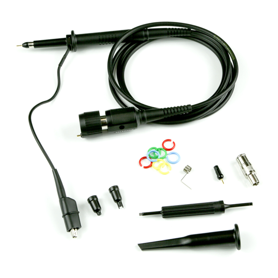
User Manual Replaceable Parts Item Description Quantity Sprung Hook, 5 mm, Black GND Lead w/Alligator Clip BNC Adapter, 5 mm Replacement Tip, Black Deluxe Trimmer Tool IC Tip Insulator, 5 mm, Black Tip Insulator, 5 mm, Black Identifier Rings Probe Tip GND Standard Accessory Replacement Kit part number is PKIT4-5MM-101. -
Page 12: Warranty
Spare parts, replacement parts and repairs are warranted for 90 days. In exercising its warranty, Teledyne LeCroy, at its option, will either repair or replace any assembly returned within the warranty period to the Customer Service Department of an authorized service center. - Page 13 Mouser Electronics Authorized Distributor Click to View Pricing, Inventory, Delivery & Lifecycle Information: Teledyne LeCroy PP019-1 PP020-1...
Need help?
Do you have a question about the PP019 and is the answer not in the manual?
Questions and answers