Table of Contents
Advertisement
Advertisement
Table of Contents

Related Manuals for Mercury Active Trim


Summary of Contents for Mercury Active Trim
- Page 1 Operation and Installation Manual...
- Page 3 Mercury gauges, controls, and rigging components—if installed on the boat at the same time as the engine—will have a standard limited warranty equal to that of the engine (if built after 5/1/2007). If purchased separately, Mercury gauges, controls, and rigging components will have a standard limited warranty of one year.
-
Page 5: Table Of Contents
Important Information Electrical Safety Requirements................1 Operation Introduction to Active Trim.................. 2 Active Trim Keypad..................... 3 Active Trim Operation..................4 Adjustable Profiles....................5 Selecting the Correct Profile................6 Troubleshooting Red Status Light Fault Codes................9 Owner Service Assistance Service Assistance................... 10 Installation Active Trim Kit Contents................... -
Page 7: Important Information
IMPORTANT INFORMATION Electrical Safety Requirements WARNING This unit has not been assessed as a safety component and is not to be relied upon as a safety device. SPECIFICATIONS IMPORTANT: Always refer to the Operation and Maintenance manual included with each engine for fuse holder location, fuse rating, and electrical system overload protection. -
Page 8: Operation
61899 At boat startup, Active Trim resumes the on/off state from the previous shut down. For example, if Active Trim was on at the previous shut down, it will be on at the next startup. -
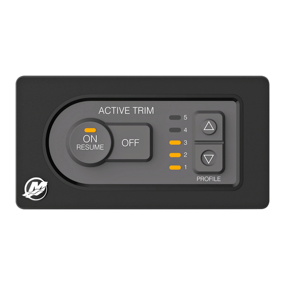
Page 9: Active Trim Keypad
Hot Start ‑ If the vessel has been keyed off for less than eight hours, the GPS will acquire a signal in less than 10 seconds. The Active Trim system will not automatically control trim until the GPS unit has acquired a signal. The system status light flashing red may indicate that no GPS signal has been acquired. -
Page 10: Active Trim Operation
Active Trim will gradually return the engine or drive to the down position during deceleration. • Active Trim will only function when the engine or drive is in the normal trim range. Refer to Trailer Position and Active Trim. NOTE: When paired with a SmartCraft gauge with an available ECO mode screen, the Active Trim system will override any ECO mode request. -
Page 11: Adjustable Profiles
TRAILER POSITION AND ACTIVE TRIM Placing the engine or drive in trailer position (over 50% of the adapted trim range) will prevent Active Trim from engaging. Any time the engine or drive is trimmed above its normal range—to navigate shallow water, launch the boat from a trailer, or load the boat onto a trailer, for example—you must manually... -
Page 12: Selecting The Correct Profile
OPERATION TRIM PROFILE ADJUSTMENT Use the Active Trim keypad Up Arrow and Down Arrow buttons to adjust the selected profile to the most efficient running attitude to compensate for changes in boat loading (passenger or gear distribution, changes in ballast or fuel tank levels), weather, propping, and operator preference. - Page 13 The engine or drive should be trimmed in for best start‑up acceleration and shortest time to plane. The engine or drive would then be trimmed out for peak performance. Active Trim automatically handles this transition for you. 61921 Engine or drive properly trimmed If the engine or drive is trimmed in too far, the bow drops and the boat runs too wet.
- Page 14 CHOOSING AN ACTIVE TRIM PROFILE If Active Trim is configured properly, the normal setting for running on plane will be profile 2, 3, or 4. This allows the operator the flexibility to change the trim angle to compensate for variations in boat loading or other operating conditions.
-
Page 15: Troubleshooting
TROUBLESHOOTING Red Status Light Fault Codes A flashing red light can indicate different things, depending on if it is a single or a double flash sequence. SINGLE FLASHING RED 61841 Light (on or off) Interval Fault Condition Description Notes GPS signal has achieved Indicates loss of GPS signal. -
Page 16: Owner Service Assistance
OWNER SERVICE ASSISTANCE Service Assistance LOCAL REPAIR SERVICE If you need service for your Mercury accessory, take it to your authorized dealer. SERVICE AWAY FROM HOME If you are away from your local dealer and the need arises for service, contact the nearest authorized dealer. - Page 17 Japan Telephone +072 233 8888 Kisaka Co., Ltd. 4‑130 Kannabecho, Sakai‑ku +072 233 8833 Sakai‑shi, Osaka 590‑0984, Japan Asia, Singapore Telephone +65 65466160 Brunswick Asia Pacific Group T/A Mercury Marine Singapore Pte Ltd 29 Loyang Drive +65 65467789 Singapore, 508944...
-
Page 18: Installation
Basic kit DTS Active Trim harness NON-DTS APPLICATIONS IMPORTANT: The Active Trim harness for non‑DTS applications is different between Outboard and MerCruiser applications, and between single and dual‑engine applications. Confirm that you have the correct harness for your application prior to beginning the installation. - Page 19 INSTALLATION 40/50/60 FourStroke Engines (Single‑Engine Only) Active Trim can be installed on 40/50/60 FourStroke engines only with serial number 1C453840 or above. Qty. Description Basic kit Active Trim harness Digital to analog converter (includes installation instructions) Digital trim sender kit...
- Page 20 INSTALLATION 61843 Basic kit contents...
-
Page 21: Installation Notes
Check the area behind the panel for cables, wiring, electronic components, and obstructions before cutting or drilling. The selection of a suitable mounting location is important for the optimal performance of the Active Trim system. The mounting location and orientation of the keypad assembly should be: •... -
Page 22: Keypad Installation
INSTALLATION • Vinyl covered—Remove vinyl from the area to be cut with a razor blade to keep vinyl from tearing. Keypad Installation FLUSH MOUNTING ON A THIN PANEL The keypad assembly can be surface mounted or flush mounted. Remove, or install the optional spacer behind the dash panel when flush mounting on a thin panel. -
Page 23: Vessel Control Module (Vcm) Installation
INSTALLATION 5. Place the keypad assembly, gasket, and spacer into the panel and secure with the retaining nut or four #8 self‑tapping screws. Plastic ring Bezel Keypad Housing Spacer #8 self‑tapping screw (4) Adhesive gasket Gasket Antirotation pin Retaining nut 61845 NOTE: The spacer can be removed or placed on the back side of the panel when flush mounting on a thin panel. -
Page 24: Harness Connections
INSTALLATION 5. Predrilling pilot holes for the screws is recommended. 59752 Wood screw (3) Washer (3) Grommet (3) Bushing (3) Bracket Screw (3) Harness Connections VCM CONNECTION (ALL MODELS) Exercise care when connecting the vessel control module (VCM) to the Active Trim harness. - Page 25 2. Ensure that the keypad assembly and VCM have been installed as previously outlined. 3. Connect the DTS Active Trim harness to the VCM. Refer to VCM Connection (All Models). 4. Connect the keypad assembly to the DTS Active Trim harness.
- Page 26 J‑box (4‑way shown, actual configuration may vary) Helm harness Trim tabs IMPORTANT: The Active Trim system will not control the trim tabs. The VCM reads the tab sensor position and transmits it on CAN P for use with SmartCraft gauges.
- Page 27 INSTALLATION WIRE COLOR CODE ABBREVIATIONS Wire Color Abbreviations Black Blue Brown GRY or GRA Gray Green ORN or ORG Orange Pink PPL or PUR Purple White Yellow LT or LIT Light DK or DRK Dark...
- Page 28 INSTALLATION OUTBOARD NON-DTS APPLICATIONS Outboard Single Engine Non‑DTS Applications, Panel or Console Control A B C A B C 61847...
- Page 29 6. For existing installations, disconnect the helm harness trim connector or connectors from the remote control. 7. Connect the Active Trim harness to the 3‑pin trim connector on the helm harness. 8. Connect the Active Trim harness to the remote control 3‑pin trim harness...
- Page 30 INSTALLATION Outboard Single Engine Non‑DTS Applications, Side Mount Control 61946...
- Page 31 2. Ensure that the keypad assembly and VCM have been installed as previously outlined. 3. Connect the Active Trim harness to the VCM. Refer to VCM Connection (All Models). 4. Connect the keypad assembly to the Active Trim harness.
- Page 32 INSTALLATION Outboard Dual Engine Non‑DTS Applications 61848...
- Page 33 Instructions are supplied with the D/A converters. 2. Ensure that the keypad assembly and VCM have been installed as previously outlined. 3. Connect the Active Trim harness to the VCM. Refer to VCM Connection (All Models). 4. Connect the keypad assembly to the Active Trim harness.
- Page 34 INSTALLATION MERCRUISER NON-DTS APPLICATIONS MerCruiser Single Engine Non‑DTS Applications 61849...
- Page 35 MerCruiser applications prior to beginning the installation. 1. Ensure that the keypad assembly and VCM have been installed as previously outlined. 2. Connect the Active Trim harness to the VCM. Refer to VCM Connection (All Models). 3. Connect the keypad assembly to the Active Trim harness.
- Page 36 INSTALLATION MerCruiser Dual Engine Non‑DTS Applications 61850...
- Page 37 MerCruiser applications prior to beginning the installation. 1. Ensure that the keypad assembly and VCM have been installed as previously outlined. 2. Connect the Active Trim harness to the VCM. Refer to VCM Connection (All Models). 3. Connect the keypad assembly to the Active Trim harness.
-
Page 38: Trim Profiles Overview
Trim Profiles Overview MAJOR TRIM PROFILE CURVES The Active Trim system can be configured to any of five unique major trim profiles. The following illustration shows how the trim angle versus boat speed curves will differ for each of the five major profiles. -
Page 39: Setup And Configuration
Range overlap of major profiles 4 and 3 Setup and Configuration CONFIGURATION NOTES IMPORTANT: A Mercury service tool is required to set up Active Trim for dual station applications or to enable the internal GPS receiver for use with SmartCraft gauges. Refer to CDS G3 Setup. - Page 40 4. Start the engine and observe the keypad. Flashing amber lights on the vertical LED trim display indicate that the Active Trim system is in the setup mode and ready for activation.
-
Page 41: Cds G3 Setup
Active Trim system's memory. The amber lights on the vertical LED trim display will stop flashing, and the display will move to the center profile position (level 3). The Active Trim is now ready to use. CDS G3 Setup NOTE: CDS G3 setup is required only for dual station applications and for enabling the GPS receiver for use with SmartCraft gauges. - Page 42 INSTALLATION • For enabling the GPS for SmartCraft gauges, select the Active Trim GPS tab found in the Trackpad Configuration screen. Follow the on‑screen instructions to enable the GPS for use with SmartCraft gauges. Only use the Active Trim GPS to provide speed information for SmartCraft gauges...
-
Page 43: Templates
INSTALLATION Templates FLUSH MOUNT IMPORTANT: Due to printing variables, the image size may have changed from the actual size. Check the graphic for accuracy prior to using the template. 61852... - Page 44 INSTALLATION SURFACE MOUNT IMPORTANT: Due to printing variables, the image size may have changed from the actual size. Check the graphic for accuracy prior to using the template. 61853...
Need help?
Do you have a question about the Active Trim and is the answer not in the manual?
Questions and answers