Table of Contents
Advertisement
Quick Links
Advertisement
Table of Contents
Troubleshooting

Related Manuals for Marport PRO SPEED


Summary of Contents for Marport PRO SPEED
-
Page 2: Table Of Contents
Contents Configuring the Echo Sounder Legal About the Automatic Range Mode History Calibrating the Sensor for Target Strength Copyright Value Disclaimer Calibrating the Speed Checking Speed Measures with EM Log Tester Applying Offsets to Measurements Introduction and Testing Measures Presentation SD Card Recording Introduction Saving a Configuration on Mosa2... - Page 3 Contents | iii Installing the Sensor on the Trawl Index Maintenance and Troubleshooting Identifying and Deactivating Sensor Alarms Checking Noise Interference Charging the Sensor with the Dock Cleaning the Sensor Maintenance Checklist Troubleshooting Mosa2 does not open due to error message Sensor does not connect correctly with Mosa2 when using the Configuration Cable The echogram has a lot of interference...
-
Page 4: Legal
Marport. “Marport”, the Marport logo and Software Defined Sonar are registered trademarks of Marport. All other brands, products and company names mentioned are the trademark and property of its respective owners only. Marport is a division of Airmar Technology Corporation. -
Page 6: Introduction And Presentation
Get a basic knowledge of the sensor. Introduction Marport's Speed Navigator is a high-definition net sounder, designed to operate on the trawl headline and tunnel. It measures the speed of the water flow in two axis: the flow along the direction of the trawl and across it. -
Page 7: Applications
Applications Examples of data received and displayed in Scala2 application. Below is an example of data received from the sensor. The autorange mode is activated, so the sounding range changes to 20, then 10 meters as the sea bottom gets closer. See About the Automatic Range Mode (on page 27) for more details about this mode. -
Page 8: Safety Guidelines
Important: To ensure proper and safe use of this equipment, carefully read and follow the instructions in this manual. Description System Compatibility The Speed Navigator is compatible with the following versions of Marport's software and equipment. Mosa2 02.11.10 or later Scala2 02.10.03 or later... -
Page 9: Firmware And Features
Firmware and Features This section describes the firmware and features that must be configured on MASP to set up the sensor. To be operational, the sensor needs to be configured with two files: • a firmware file (*.A2F): it is the firmware of the sensor, •... -
Page 10: Technical Specifications
Measures • Battery (always activated) • Across Speed (always activated) • Along Speed (always activated) • Pressure (depth) • Temperature • Pitch • Roll Technical Specifications Uplink frequency 30 to 60 kHz Range to vessel up to 2500 m* • 5-meter range: Echogram @0.16 s - temperature, depth, pitch, roll, Data update rate battery level, along speed, across speed @8.07 s •... - Page 11 *Reference only. Depends on communication settings and transmission conditions / † Depends on sensor uplink power and options. Lifetime has been estimated with a uplink power at 33%. / ‡ Based on average charging time. / **Marport Standard Marine Limited Warranty...
-
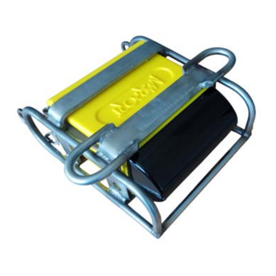
Page 12: Main Parts
Setup with a board for a reversed installation: Main Parts External View 1. Temperature sensor 6. Pressure-relief spring 2. Negative charge 7. Pressure sensor 3. Water switch 8. EM log pins 4. Positive charge 9. Latch 5. Shoulder bolts Exploded View 1. - Page 13 PCBA Connectors The Speed Navigator has two PCBAs: • PCBA version A2S Gen 4 (P/N 25-1023-04) and after: 1. Batteries 2. Connection to Sarah Connor PCBA 3. Water-switch 4. Down (A) 5. Up (B) 6. Uplink (C) 7. Temperature and pressure (T&D) •...
-
Page 15: Sensor Configuration
Sensor Configuration Learn how to configure the sensor settings. To be able to change the settings of the sensor: Press command + A or click Menu and click User Mode > Advanced. Connecting the Sensor to Mosa2 To configure the sensor, you need to connect it to Mosa2 application, using either the Dock or the Configuration Cable. - Page 16 1. Connect one Dock charging plug to the sensor's endcap. 2. Mosa2 discovery page opens. The sensor is displayed. ◦ Click to open the sensor configuration page. ◦ Click to show the deploy animation on the charger plug for 30 seconds. Using the Configuration Cable Simply connect the Configuration Cable from the computer to the sensor to display the sensor configuration page on Mosa2.
- Page 17 Mosa2 opens automatically and the startup wizard is displayed. The LED on the plug is solid blue. 3. Connect the three-pin plug to the sensor. The LED on the plug blinks alternatively blue and green. 4. Wait a few seconds. The configuration page of the sensor is displayed on Mosa2. The LED on the plug is solid green.
-
Page 18: Battery Information
Battery Information The battery lifetime is displayed on the first page. Speed Navigator | V1 | Sensor Configuration... -
Page 19: Diagnostic Information
Diagnostic Information Scala2 and Mosa2 applications warn the user in case of water ingress in the sensor. Note: Diagnostic information is available for Marport Pro sensors (A2S and A2H PCBA versions), from the firmware version F450-02.02.00 or later and Mosa2 version 02.11.08. -
Page 20: Uploading The Sensor Firmware
In case of water ingress in the sensor, alarms are displayed in Scala2 Virtual Charger Room, in Mosa2 and on the charger plug when connected to the sensor. • Mosa2 displays a dialog at the start of the application and warning icon in the toolbar and diagnostic page: •... - Page 21 Downloading the Firmware and Application Files Note: Marport offices only. Only Marport offices can download new versions of firmware. Dealerships need to ask their local Marport office to get the firmware. 1. From a web browser, go to Marport Authorized Service Provider (MASP) website: https://asp.marport.fr/.
- Page 22 6. To manually configure the application, first enter the complete name of the sensor in Product name. Then, complete the options. Note: See Firmware and Features (on page 9) for details about the options. Updating the Sensor with the Configuration Cable 1.
-
Page 23: Configuring The Trawl Node
Configuring the Trawl Node You need to give a trawl node to the sensor. It is the number corresponding to the position of the sensor on the trawl. The trawl nodes corresponding to the positions on the headline and tunnel are the following: Node numbers Node numbers... -
Page 24: Configuring The Uplink Frequency And Power
1. Go to the Communication page, then click in Uplink. 2. Enter a node according to the position of the sensor on the trawl. Important: Make sure to put the same number when adding the sensor to Scala2 receiver page. If not, change it accordingly. 3. -
Page 25: Configuring The Echo Sounder
1. Go to the Communication page, then click in Uplink. 2. Enter a frequency for the communication with the vessel. Default is 44,000 Hz. 3. Drag the slider to change the power of the uplink signal. Note: A higher level of uplink power reduces the battery lifetime. Recommended Conditions uplink powers... - Page 26 in Down Sounding or Up Sounding, 3. Go back to the page, then click depending on the Sounding Mode that was configured. 4. Set the Frequency (Hz) at 165,000 Hz. 5. The Range (m) of the sounding is the maximum distance at which targets and bottom can be detected.
-
Page 27: About The Automatic Range Mode
◦ 20 log: focus on bottom or school of fish. ◦ 40 log: focus on individual targets. ◦ 30 log: compromise between the two above settings. 8. Do not modify the other echo sounder settings. About the Automatic Range Mode The sensor has an automatic range mode that is useful to get better quality echograms when the trawl is close to the bottom. - Page 28 On the example below, you can see the range changing as the sensor gets closer to the sea bottom. The sensor is configured with a 40-meters sounding range and 1.5-meter trawl opening. 1. Maximum range / 2. Switch to a 20-meter range / 3. Switch to a 10-meter range / 4. Switch to a 5-meter range Mosa2 settings The following Sounding Mode options must be set in Mosa2:...
-
Page 29: Calibrating The Sensor For Target Strength
See Configuring the Echo Sounder (on page 25) for details about Mosa2 settings. Calibrating the Sensor for Target Strength Value You need to calibrate the sensor to offset the variability of the sensor transducer and of sound transmission. The aim is to have all sensors displaying the same target strength value (echogram color) for a given target. - Page 30 2. Before putting the sensor in water, connect the cable extension to the bottle. 3. Connect the Configuration Cable or a Dock charger plug to the other end of the cable extension. If applicable, connect the Configuration Cable to the computer. Notice: The Configuration Cable and charger plugs are not waterproof: do not immerse them.
- Page 31 10. Make sure Disable Waterswitch is activated. This prevents the sensor from switching into running mode when the endcap is wet or immersed. 11. Now you can put the sensor into water. Calibrating the Sensor in Mosa2 1. By default, the Distance from sensor to the target (cm) is 50 cm and the Expected target strength (dB) is -39 dB (target strength value of a ping pong ball of 39 mm diameter).
- Page 32 3. From the bottom of the screen, click Send ping to send one ping that will identify the distance to the target. A curve is displayed. Click anywhere on the graph to show the green markers. The horizontal line indicates the target strength and the vertical line indicates the distance.
- Page 33 A new target strength offset is calculated. 5. Accept the new calibration settings suggested in the dialog box. The gain correction is auto-populated. Speed Navigator | V1 | Sensor Configuration...
-
Page 34: Calibrating The Speed
The sensor sends 1 ping to check if the calibration settings are correct in comparison to the target strength set (e.g. -39 dB). If they are correct, calibration settings are saved. If calibration settings are not correct, check the installation in the water tank. Then restart the calibration procedure. - Page 35 When the sensor is in water without any current, it must measure ± 0.1 knot max. for along and across speeds. But because of the variability of the sensor components, it may still measure higher levels of speed. The aim of calibration is to apply an offset so that the sensor measures the correct speeds.
-
Page 36: Tester
Mosa2 calculates the offset, applies it to the sensor and the sensor sends again measures with the offset applied. 8. Marport offices only: Save the configuration file and add it to the sensor page in MASP, in Attachments > Miscellaneous. - Page 37 If you do not have the EM Log tester, please refer to your local Marport sales office. The EM Log tester is also useful to check that the sensor is still operational over time. You can check speed before every fishing campaign to make sure the sensor works properly.
-
Page 38: Applying Offsets To Measurements
4. Click EMlog Test. The along speed must be between 2 and 3 knots for a standard installation (1.10 Along Gain) and 2.5 to 3.8 for a reversed installation (1.26 Across Gain), and the across speed must be between -3 and -2 knots. Troubleshooting: If the along speed is negative and the across speed positive, it means that you placed the EM Log tester upside down. - Page 39 1. Go to Measurements page and click next to depth or temperature to apply offsets. 2. Enter a target value. Click The measured value becomes the same as the target value. The value of the offset is displayed. 3. If you need to reuse offsets from a previous configuration, click then select the configuration file (*.A2C).
-
Page 40: Testing Measures
Testing Measures You can test the measures taken by the sensor (e.g. battery level, temperature, depth) to check that there are no faults. You can test the sensor in water or in air. In air, the following measures will be wrong: height, conductivity. -
Page 41: Sd Card Recording
4. Click to check and, if necessary, adjust data measured by the sensor: ◦ Depth: Place your sensor on a desk or on the ground and enter 0 in Target Depth. ◦ Temperature: Enter the estimated temperature of your environment. SD Card Recording This topic explains the SD card recording feature (this feature is optional). - Page 42 1. Go to the Communication page, then click in Recording. 2. Activate Additional support Log. Getting data from the SD card The last 99 recorded sensor data files and last 99 battery files are displayed. Two types of files are on the SD card: •...
-
Page 43: Saving A Configuration On Mosa2
Recorded files are displayed. Click the title of the columns to sort them by their name, date or size. 1. Time of end of towing 2. Free memory on SD card 3. Memory size of SD card 4. Index of the last SD card file written See Replaying Data from A2S Files (on page 58) to learn how to replay these data in Scala2. - Page 44 configured the sensor on a computer at the office before installing it on a vessel, you need to also save the configuration on the vessel's computer. You can have up to three different configurations for the sensor. When you change your fishing method, you can apply a corresponding configuration in one click.
- Page 45 3. To create another configuration, for example this time to use the sensor in deep waters, change the settings of the sensor on Mosa2. 4. When you are finished, click the second wheel icon and save the configuration. 5. If you need to change the sensor configuration back to the first configuration (shallow water), click the corresponding wheel.
-
Page 46: Exporting Sensor Configuration
Exporting Sensor Configuration You can export the sensor settings you configured on Mosa2 on a file. You can afterward use this file when configuring a similar sensor. • You are finished configuring the sensor. If you have issues with your sensor, send this file to support teams. 1. - Page 47 Only the following settings are imported: trawl node, recording settings (SD card, support logs), communication options (virtual water switch, simulation mode), uplink level and frequency, echo sounder settings. Important: If the new configuration changes the echo sounder settings, you must re-calibrate the sensor for target strength value. 1.
-
Page 49: System Configuration And Display
System Configuration and Display Learn how to configure the receiver and display the sensor data in Scala2 application. Adding the Sensors to the Receiver You need to add the sensors to the receiver in order to display their data on Scala2. Adding the Sensors to the Receiver You need to add the sensors to the receiver using the system web page. -
Page 50: Configuring The Sensor Settings
Configuring the Sensor Settings You need to complete communication settings when you add the sensor to the receiver. Important: Make sure the settings you enter here are the same as in Mosa2. Sensor name displayed in Scala2 and its features. Enter the same frequency as the one entered for the uplink frequency in Mosa2. -
Page 51: Configuring Data Display In Scala2
Click Configure to change filters applied on incoming data. Filters are particularly useful to re duce interferences on the echogram data. Note: Be aware that echogram filters such as Echosounder and Interference Reduction may remove small targets on the echogram. Tip: Please refer to Scala2 user guide for more information about the filters. - Page 52 3. Click + hold other data, such as depth, pitch, roll, and drag it as well to the page display. 4. Select the type of display. 5. To display the Water Speed Along and Water Speed Across data in 3D views: Speed Navigator | V1 | System Configuration and Display...
- Page 53 a. Open the customization panels and go to the MX tab. b. Click + hold TS Dial or TS 3D and drag it to the page. Note: On the TS Dial, the bearing angle is negative when the sensor is oriented toward port and positive when oriented toward starboard.
- Page 54 6. Drag the lines around the blocks of data to resize them. Speed Navigator | V1 | System Configuration and Display...
-
Page 55: Outputting Scala2 Symmetry Data To Scantrol
You can output across speed data from Scala2 to Scantrol iSYM application. • You need to have iSYM version 3.5.10 (beta version) and above • Make sure you have a license to use Marport software with Scantrol. Speed Navigator | V1 | System... - Page 56 1. Scantrol and Marport computers must be connected together via an Ethernet wired network. Both computers must be on the same sub-network to communicate with each other: 192.168.0.XX. For example, the network IP address can be set at 192.168.0.10 on Scantrol computer and at 192.168.0.12 on Marport computer.
- Page 57 Select Emit only selected data types, then select Water Speed Along and Water Speed Across. 6. Go to iSYM's System Settings. 7. Go to Trawl Sensors tab, then select Marport in Active sensor source. Speed Navigator | V1 | System Configuration and Display...
-
Page 58: Replaying Data From A2S Files
8. Configure the communication settings in Trawl sensor communication. Enter the same port you set in Scala2. Note: Port closed mention at the bottom of the window does not impact the configuration and should be ignored. Tip: If you need to test the NMEA connection but the sensors are not in water: configure the same output settings in ScalaReplay2, then replay SDS files containing data. - Page 59 1. Download A2S files from Mosa2 2. Right-click the timeline and click Change Directory to choose the source directory where A2S files are stored. In the replay bar, the recording period of A2S files is displayed in green. In the control panels, data that were received in live are displayed in the Mx panel and data recorded on the SD card are displayed in the A2S Data panel.
-
Page 61: Installation
Make sure to always use a protective cage when using the sensor. The protective cage must be approved by Marport. Any additional protective devices installed in front of the head may disrupt the flow and therefore alter the water speed measurements. - Page 62 When the sensor is installed on the headrope, you may not see the footrope. If you want to see it, move back the sensor of a few meters. The sensor must be placed in a way that there is less than +/- 5 degrees of pitch and roll. You may need to add floats to the back of the sensor to achieve this.
- Page 63 Reversed Installation In this installation, the EM log pins face up instead of down. In this case, the Speed Navigator is installed on a board to provide more stability. The aim of this installation is to prevent the EM log pins and transducer to hit the deck when the trawl is hauled. 1.
-
Page 65: Maintenance And Troubleshooting
Maintenance and Troubleshooting Read this section for troubleshooting and maintenance information. Identifying and Deactivating Sensor Alarms The Diagnostic page in Mosa2 shows if water ingress has been detected or not. 1. Go to the Diagnostic page. 2. If the water ingress alarm is activated, take the sensor out of water, check the bottle and repair it. - Page 66 1. Click Add to create a new page on which you will add the spectrum analyzer(s). 2. Right-click the IP address of the receiver in the status bar and click Start Spectrum. 3. Open the control panels and go to the Mx panel. 4.
- Page 67 5. The spectrum analyzer is displayed. You can display up to 6 spectrum analyzers at the same time. Below is an example of a page with two spectrum analyzers. The FFT plot shows three levels of noise in dBV: a. RealTime (white): level of noise recorded in real time. b.
- Page 68 ◦ RealTime: the latest highest level of noise (dBV) record ed and its frequency. ◦ Max: the highest level of noise recorded since the begin ning of the spectrum and its frequency. 8. Check that there is more than 12 dBV between the maximum noise level (dark blue line) and the average noise level (cyan line) on the peak of sensor frequencies.
-
Page 69: Charging The Sensor With The Dock
The FFT file lists for the entire bandwidth used by the hydrophone (frequencies are in Hz) the maximum and mean levels of noise since the FFT export has started and the last real time level of noise before the export (dBV). 13. -
Page 70: Cleaning The Sensor
Important: Check that the charging pins are not damaged. If they are, contact you local Marport dealer for replacement. 2. Connect the charger plug to one of the 4 charging ports. 3. Connect the 3-pin charging connector to the sensor charging pins. -
Page 71: Maintenance Checklist
• Wash away mud or debris with warm water. • Use Isopropyl alcohol to clean the end cap and transducer. Use a steel wool pencil to clean the shoulder bolts, and very fine sandpaper (180 grit) to clean between them. Notice: Do not use highly abrasive materials or jet wash. -
Page 72: Troubleshooting
• Do not leave the batteries at full charge or Not used for more than 3 months discharged for a long period of time or they will wear out. • Every 6 months, put the sensor in charge for less than an hour. Every 2 years The sensor must be returned to an approved Mar... -
Page 73: Sensor Does Not Connect Correctly With Mosa2
• Make sure the three pins are fully inserted inside the sensor. Mosa2 does not automatically open when connecting the Configuration Cable. • Check that you see Marport Captain icon in the desktop taskbar. If you do not see it: close, then open Mosa2. The icon should appear in the taskbar. -
Page 74: The Echogram Has A Lot Of Interference
• Disconnect both USB connector and three-pin plug. Then, connect again the Configuration Cable. If the message is still displayed, it means there is an issue with the sensor’s components. Contact Marport support. The echogram has a lot of interference There are interference from environmental noise or other equipment such as echosounders. - Page 75 1. From Scala2, click Menu > Expert Mode and enter the password copernic 2. Right-click the IP address of the receiver at the bottom of the page, then click Configure Receiver. 3. Click the name of the sensor in the system tree view. 4.
-
Page 76: Speed Data Is Wrong
Speed data is wrong Speed data displayed in Scala2 is wrong. By default in Scala2, speed units of measure are in meter/second. If you are used to knots, these measures will seem too low. 1. Check the units of measure. 2. -
Page 77: Support Contact
Support Contact You can contact your local dealer if you need maintenance on your Marport products. You can also ask us at the following contact details: FRANCE ICELAND Marport France SAS Marport EHF 8, rue Maurice Le Léon Tónahvarf 7... -
Page 78: Appendix
You can create a table with a list of frequencies and complete it when you add sensors. Frequencies and intervals The diagrams below show the bandwidth of the different types of Marport sensors and intervals you must respect when adding other sensors. Figure 1. PRP sensors (e.g. Catch sensor, Trawl Speed, Spread sensor...) Example: If the frequency of the sensor is 40kHz, there should be no sensors between 39.9-40kHz and 40-40.1kHz. - Page 79 Figure 3. NBTE sensors (e.g. Speed Explorer, Trawl Explorer, Catch Explorer, Catch Navigator, Door Sounder) Example: If the frequency of the sensor is 40kHz, there should be no sensors between 39.8-40kHz and 40-40.6kHz. Figure 4. HDTE narrow band mode Example: If the frequency of the sensor is 40kHz, there should be no sensors between 39.8-40kHz and 40-41kHz.
- Page 80 Examples of frequency allocations • We recommend to allocate frequencies between 34 and 56 kHz for wideband hydrophones and between 41 kHz and 44 kHz for narrowband hydrophones. • Echosounders are usually placed around 38 kHz, make sure to allow enough distance with them.
- Page 81 Example of a system with Spread, Catch, Trawl Speed sensors and Speed Explorer, Catch Explorer, HDTE and Door Sounder. Example of a system with Spread sensors with positioning, Catch sensors, Trawl Explorer and Catch Explorer. Speed Navigator | V1 | Appendix...
- Page 82 Example of a system for purse seining, with a Seine Explorer and depth Seine sensors. Bandwidth Mandatory distance with other sensors Avoid allocating frequencies between 37 and 39 kHz because this range is generally used by echosounders. Speed Navigator | V1 | Appendix...
-
Page 83: Examples Of Installations For A Target
Examples of Installations for a Target Strength Calibration Support for sensor Figure 6. Example of support for a speed sensor (down and up sounding) Figure 7. Example of support Speed Navigator | V1 | Appendix... - Page 84 Figure 8. Example of support Speed Navigator | V1 | Appendix...
- Page 85 Ping pong ball Figure 9. Fishing line passes through the ball and is fixed with glue. Speed Navigator | V1 | Appendix...
- Page 86 Figure 10. Example of installation with counterweights. 1. 50 cm 2. 1 m 3. Counterweight Speed Navigator | V1 | Appendix...
-
Page 87: Calibration
Examples of Installations for a Speed Calibration Figure 11. Example of supports for a reversed installation Speed Navigator | V1 | Appendix... - Page 88 Speed Navigator | V1 | Appendix...
- Page 89 Index Charging see D ock Across speed 34 Cleaning 70 Alarms Configuration Cable 15 Concept 19 Troubleshooting 73 Deactivating Unknown 65 Along speed 34 Application Update 20 Upload 20 Depth sensor 12 Automatic range 27 Diagnostic 19, 65 Display Echogram 51 TS 3D 51 TS Dial 51 Water Speed Across 51 Battery Water Speed Along 51 Lifetime 18 Dock Boat code 78...
- Page 90 Update 20 Depth 38 Upload 20 Temperature 38 Frequency plan 78 PCBA Interference A2S 12 Checking 65 Connectors 12 Sarah Connor 12 Positive charge 12 Maintenance Schedule 71 Measures 40 Receiver Mosa2 Adding to 49 Opening 15 Compatibility 49 Mosa2 configuration Compatible firmware 49 Change 43 Sensor settings 50 Delete 43 Replay Export 46 A2S files 58 Import 46 Save 43 SA606 calibration 38 Scala2 51 Negative charge 12 SD card...
- Page 91 Frequency 25 Length 25 Range 25 TVG 25 Up 25 Spectrum 65 Speed check 36 Temperature sensor 12 Trawl Node 23 Uplink Frequency 24 Power 24 Warning 19 Water switch 12...
Need help?
Do you have a question about the PRO SPEED and is the answer not in the manual?
Questions and answers