Table of Contents
Advertisement
Quick Links
Blast Chiller
EN
Handleiding
Vriezer
NL
Handleiding
Congélateurs
FR
Mode d'emploi
Model • Modèle • Modell • Modello • Modelo • Malli:
UA014-UA015-UA016_ML_A5_v3_20221027.indb 1
UA014-UA015-UA016_ML_A5_v3_20221027.indb 1
2
DE
12
IT
22
ES
UA014/UA015/UA016
Blast Chiller
Instruction manual
Tiefkühltische
Bedienungsanleitung
Congelatori
Manuale di istruzioni
Congeladores
Manual de instrucciones
32
42
52
2022/10/27 16:56
2022/10/27 16:56
Advertisement
Table of Contents

Subscribe to Our Youtube Channel
Related Manuals for Polar Electro UA014


Summary of Contents for Polar Electro UA014
- Page 1 Instruction manual Blast Chiller Tiefkühltische Handleiding Bedienungsanleitung Vriezer Congelatori Handleiding Manuale di istruzioni Congélateurs Congeladores Mode d'emploi Manual de instrucciones Model • Modèle • Modell • Modello • Modelo • Malli: UA014/UA015/UA016 UA014-UA015-UA016_ML_A5_v3_20221027.indb 1 UA014-UA015-UA016_ML_A5_v3_20221027.indb 1 2022/10/27 16:56 2022/10/27 16:56...
-
Page 2: Safety Instructions
• If the power cord is damaged, it must be replaced by a POLAR agent or a recommended qualified technician in order to avoid a hazard. UA014-UA015-UA016_ML_A5_v3_20221027.indb 2 UA014-UA015-UA016_ML_A5_v3_20221027.indb 2 2022/10/27 16:56 2022/10/27 16:56... -
Page 3: Product Description
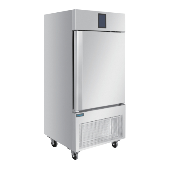
Product Description UA014 - POLAR Blast Chiller with Touch screen Controller (3 x 1/1GN) UA015 - POLAR Blast Chiller with Touch screen Controller (5 x 1/1GN) UA016 - POLAR Blast Chiller with Touch screen Controller (10 x 1/1GN) Introduction Please take a few moments to carefully read through this manual. -
Page 4: Pack Contents
Note: To prevent bacterial contamination Polar agent. or contamination of any other biological • For details, please refer to instructions on nature, the needle probe must be Pages 62-65. disinfected after use. UA014-UA015-UA016_ML_A5_v3_20221027.indb 4 UA014-UA015-UA016_ML_A5_v3_20221027.indb 4 2022/10/27 16:56 2022/10/27 16:56... -
Page 5: Unlock Keypad
If the power supply fails during “stand-by” or appear on the display. Press any area on the “on” mode, when power is restored the device display to remove this signal. will return to the mode set before the failure. UA014-UA015-UA016_ML_A5_v3_20221027.indb 5 UA014-UA015-UA016_ML_A5_v3_20221027.indb 5 2022/10/27 16:56 2022/10/27 16:56... -
Page 6: Selecting The Operating Mode
This area will appear if an alarm is activated. Press this area to see the historical data stored during operation. (For details, see Sections 7.6.2 and 12.2 in the controller manual supplied with the appliance.) UA014-UA015-UA016_ML_A5_v3_20221027.indb 6 UA014-UA015-UA016_ML_A5_v3_20221027.indb 6 2022/10/27 16:56 2022/10/27 16:56... -
Page 7: Cleaning, Care And Maintenance
Rub with the grain of the metal, rather than across it. • Use detergents and polish designed for cleaning Stainless Steel. • Ensure that the cleaning products are washed off fully and that the steel is left dry. UA014-UA015-UA016_ML_A5_v3_20221027.indb 7 UA014-UA015-UA016_ML_A5_v3_20221027.indb 7 2022/10/27 16:56 2022/10/27 16:56... -
Page 8: Cleaning The Evaporator
3. It is now possible to clean the finned part of the condenser (D) using suitable tools and protection devices. 4. After cleaning, close the control panel and fix it with the screws removed beforehand. UA014-UA015-UA016_ML_A5_v3_20221027.indb 8 UA014-UA015-UA016_ML_A5_v3_20221027.indb 8 2022/10/27 16:56... -
Page 9: Troubleshooting
The appliance is There is a problem with the unit See table below beeping and there is a being indicated by the control message appearing on alarm signal the control panel UA014-UA015-UA016_ML_A5_v3_20221027.indb 9 UA014-UA015-UA016_ML_A5_v3_20221027.indb 9 2022/10/27 16:56 2022/10/27 16:56... - Page 10 Chiller full load capacity Freezer full load capacity UA014 90 min (12kg) 240 min (8kg) 12kg UA015 90 min (18kg) 240 min (14kg) 18kg 14kg UA016 90 min (40kg) 240 min (28kg) 40kg 28kg UA014-UA015-UA016_ML_A5_v3_20221027.indb 10 UA014-UA015-UA016_ML_A5_v3_20221027.indb 10 2022/10/27 16:56 2022/10/27 16:56...
-
Page 11: Electrical Wiring
POLAR. Every effort is made to ensure all details are correct at the time of going to press, however, POLAR reserve the right to change specifications without notice. UA014-UA015-UA016_ML_A5_v3_20221027.indb 11 UA014-UA015-UA016_ML_A5_v3_20221027.indb 11 2022/10/27 16:56... - Page 12 • Indien de stroomkabel beschadigd raakt, dient men deze door een POLAR technicus of een aanbevolen vaktechnicus te laten vervangen om gevaarlijke situaties te verhinderen. UA014-UA015-UA016_ML_A5_v3_20221027.indb 12 UA014-UA015-UA016_ML_A5_v3_20221027.indb 12 2022/10/27 16:56 2022/10/27 16:56...
- Page 13 • Waarschuwing: Gebruik geen elektrische apparaten in de bewaarruimte voor voedsel van het apparaat. Productbeschrijving UA014 - POLAR Vriezer met touchscreen bediening (3 x 1/1GN) UA015 - POLAR Vriezer met touchscreen bediening (5 x 1/1GN) UA016 - POLAR Vriezer met touchscreen bediening (10 x 1/1GN) Inleiding Neem de tijd om deze handleiding aandachtig door te lezen.
-
Page 14: Omkeren Van De Deur
Polar. functioneren. • Raadpleeg de instructies op pagina’s 62-65. Opmerking: Om bacteriële besmetting of contaminatie van elke andere biologische Bediening aard te voorkomen moet de naaldsonde gedesinfecteerd worden na ieder gebruik. UA014-UA015-UA016_ML_A5_v3_20221027.indb 14 UA014-UA015-UA016_ML_A5_v3_20221027.indb 14 2022/10/27 16:56 2022/10/27 16:56... - Page 15 “Stand-by” of “Aan” modus, zal het apparaat na het herstellen van de stroomvoorziening willekeurige plaats op het beeldscherm om dit terugkeren naar de modus, die was ingesteld signaal te verwijderen. vóór de storing. UA014-UA015-UA016_ML_A5_v3_20221027.indb 15 UA014-UA015-UA016_ML_A5_v3_20221027.indb 15 2022/10/27 16:56 2022/10/27 16:56...
- Page 16 Druk op dit gebied om de historische gegevens te zien die tijdens het gebruik zijn opgeslagen. (Zie paragrafen 7.6.2 en 12.2 in de bedieningshandleiding, die bij het apparaat is geleverd, voor meer informatie.) UA014-UA015-UA016_ML_A5_v3_20221027.indb 16 UA014-UA015-UA016_ML_A5_v3_20221027.indb 16 2022/10/27 16:56 2022/10/27 16:56...
-
Page 17: Reiniging, Zorg & Onderhoud
• reinigings- en poetsmiddelen gebruiken die speciaal voor roestvrij staal zijn bedoeld; • ervoor zorgen dat de reinigingsproducten volledig worden afgespoeld en dat het staal droog achter blijft. UA014-UA015-UA016_ML_A5_v3_20221027.indb 17 UA014-UA015-UA016_ML_A5_v3_20221027.indb 17 2022/10/27 16:56 2022/10/27 16:56... - Page 18 3. Het is nu mogelijk om de vinnen van de condensor (D) met geschikt gereedschap en beveiliging te reinigen. 4. Na het reinigen; sluit het bedieningspaneel en bevestig het met de schroeven die hiervoor werden verwijderd. UA014-UA015-UA016_ML_A5_v3_20221027.indb 18 UA014-UA015-UA016_ML_A5_v3_20221027.indb 18 2022/10/27 16:56 2022/10/27 16:56...
-
Page 19: Oplossen Van Problemen
Een cyclus selecteren) het toestel Het apparaat piept Er is een probleem met het Zie onderstaande tabel en er verschijnt een apparaat wat wordt aangegeven boodschap op het door het controle alarmsignaal bedieningspaneel UA014-UA015-UA016_ML_A5_v3_20221027.indb 19 UA014-UA015-UA016_ML_A5_v3_20221027.indb 19 2022/10/27 16:56 2022/10/27 16:56... -
Page 20: Technische Specificaties
Snelheid vriezer Koelvermogen bij volle belasting Volledige capaciteit vriezer UA014 90 min. (12kg) 240 min. (8kg) 12kg UA015 90 min. (18kg) 240 min. (14kg) 18kg 14kg UA016 90 min. (40kg) 240 min. (28kg) 40kg 28kg UA014-UA015-UA016_ML_A5_v3_20221027.indb 20 UA014-UA015-UA016_ML_A5_v3_20221027.indb 20 2022/10/27 16:56 2022/10/27 16:56... -
Page 21: Elektrische Bedrading
Wij hebben er alles aan gedaan om er zeker van te zijn dat op publicatiedatum van de handleiding alle details correct zijn, desondanks, behoudt Polar het recht voor om specificaties zonder aankondiging te wijzigen. UA014-UA015-UA016_ML_A5_v3_20221027.indb 21 UA014-UA015-UA016_ML_A5_v3_20221027.indb 21 2022/10/27 16:56... -
Page 22: Conseils De Sécurité
• Gardez les emballages hors de portée des enfants. Débarrassez-vous des emballages onformément aux règlements des autorités locales. • Un cordon d’alimentation endommagé doit être remplacé par un agent POLAR ou un technicien qualifié recommandé, pour éviter tout danger. UA014-UA015-UA016_ML_A5_v3_20221027.indb 22 UA014-UA015-UA016_ML_A5_v3_20221027.indb 22 2022/10/27 16:56 2022/10/27 16:56... -
Page 23: Description Du Produit
Description du produit UA014 - Refroidisseur POLAR Blast avec contrôleur à écran tactile (3 x 1/1GN) UA015 - Refroidisseur POLAR Blast avec contrôleur à écran tactile (5 x 1/1GN) UA016 - Refroidisseur POLAR Blast avec contrôleur à écran tactile (10 x 1/1GN) Introduction Nous vous invitons à... - Page 24 • Pour plus de détails, veuillez-vous reporter aux bactérienne ou la contamination de toute instructions contenues dans les pages 62-65. autre nature biologique, la sonde de pénétration doit être désinfectée après utilisation. UA014-UA015-UA016_ML_A5_v3_20221027.indb 24 UA014-UA015-UA016_ML_A5_v3_20221027.indb 24 2022/10/27 16:56 2022/10/27 16:56...
-
Page 25: Interface Utilisateur
Si l’alimentation électrique fait défaut pendant le mode «Veille» ou «Marche», lorsque sur l’écran. Appuyez sur n’importe quelle l’alimentation est rétablie, l’appareil revient au mode défini avant la panne. zone de l’écran pour supprimer ce signal. UA014-UA015-UA016_ML_A5_v3_20221027.indb 25 UA014-UA015-UA016_ML_A5_v3_20221027.indb 25 2022/10/27 16:56 2022/10/27 16:56... -
Page 26: Sélection Du Mode De Fonctionnement
Cette zone apparaît si une alarme est activée. Appuyez sur cette zone pour voir les données historiques enregistrées pendant le fonctionnement. (Pour plus de détails, voir les sections 7.6.2 et 12.2 du manuel du contrôleur fourni avec l’appareil). UA014-UA015-UA016_ML_A5_v3_20221027.indb 26 UA014-UA015-UA016_ML_A5_v3_20221027.indb 26 2022/10/27 16:56 2022/10/27 16:56... -
Page 27: Nettoyage, Entretien Et Maintenance
Frotter dans le sens du grain du métal et non l’inverse • Utiliser des détergents et produits d’entretien spécialement conçus pour l’inox • Veiller à bien rincer les produits de nettoyage et à essuyer l’inox UA014-UA015-UA016_ML_A5_v3_20221027.indb 27 UA014-UA015-UA016_ML_A5_v3_20221027.indb 27 2022/10/27 16:56 2022/10/27 16:56... -
Page 28: Nettoyage De L'évaporateur
3. Il est maintenant possible de nettoyer la partie à ailettes du condenseur (D) à l’aide des outils et dispositifs de protection appropriés. 4. Après le nettoyage, fermer le panneau de commande et le fixer avec les vis retirées au préalable. UA014-UA015-UA016_ML_A5_v3_20221027.indb 28 UA014-UA015-UA016_ML_A5_v3_20221027.indb 28 2022/10/27 16:56... -
Page 29: Dépannage
L’appareil émet un bip Il y a un problème qui est indiqué Voir le tableau ci-dessous et un message apparaît par le signal d’alarme du panneau sur le panneau de commande UA014-UA015-UA016_ML_A5_v3_20221027.indb 29 UA014-UA015-UA016_ML_A5_v3_20221027.indb 29 2022/10/27 16:56 2022/10/27 16:56... -
Page 30: Spécifications Techniques
UA014 90 min. (12kg) 240 min. (8kg) 12kg UA015 90 min. (18kg) 240 min. (14kg) 18kg 14kg UA016 90 min. (40kg) 240 min. (28kg) 40kg 28kg UA014-UA015-UA016_ML_A5_v3_20221027.indb 30 UA014-UA015-UA016_ML_A5_v3_20221027.indb 30 2022/10/27 16:56 2022/10/27 16:56... -
Page 31: Raccordement Électrique
Nous nous efforçons, par tous les moyens dont nous disposons, de faire en sorte que les détails contenus dans le présent mode d’emploi soient corrects en date d’impression. Toutefois, POLAR se réserve le droit de changer les spécifications de ses produits sans préavis. UA014-UA015-UA016_ML_A5_v3_20221027.indb 31 UA014-UA015-UA016_ML_A5_v3_20221027.indb 31 2022/10/27 16:56... - Page 32 Netzstecker ziehen. • Verpackungsmaterial außerhalb der Reichweite von Kindern aufbewahren und gemäß den lokalen Vorschriften entsorgen. • Aus Sicherheitsgründen muss ein beschädigtes Stromkabel von einem POLAR-Mitarbeiter oder empfohlenen qualifizierten Elektriker erneuert werden. UA014-UA015-UA016_ML_A5_v3_20221027.indb 32 UA014-UA015-UA016_ML_A5_v3_20221027.indb 32 2022/10/27 16:56 2022/10/27 16:56...
- Page 33 • Warnung: Beschädigen Sie den Kältemittelkreislauf nicht. • Warnung: Verwenden Sie keine elektrischen Geräte innerhalb der Ablagefächer des Geräts. Product Description UA014 - POLAR-Schnellkühler Berührungsbildschirmsteuerung (3 x 1/1GN) UA015 - POLAR-Schnellkühler Berührungsbildschirmsteuerung (5 x 1/1GN) UA016 - POLAR-Schnellkühler Berührungsbildschirmsteuerung (10 x 1/1GN) Einführung Bitte nehmen Sie sich einige Minuten Zeit und lesen Sie dieses Handbuch sorgfältig durch.
-
Page 34: Betrieb
Techniker, kontaktieren Sie bitte einen Hinweis: Um eine bakterielle oder andere Polar-Vertreter. biologische Verunreinigung zu vermeiden, • Einzelheiten finden Sie in den Anweisungen auf muss die Sonden-Nadel nach der Nutzung den Seiten 62-65. desinfiziert werden. UA014-UA015-UA016_ML_A5_v3_20221027.indb 34 UA014-UA015-UA016_ML_A5_v3_20221027.indb 34 2022/10/27 16:56 2022/10/27 16:56... - Page 35 Display das Signal . Drücken Sie jeglichen ausfallen, so kehrt das Gerät nach dem Wiederherstellen der Stromversorgung in den vor Bereich des Displays, um dieses Signal zu beenden. dem Stromausfall verwendeten Modus zurück. UA014-UA015-UA016_ML_A5_v3_20221027.indb 35 UA014-UA015-UA016_ML_A5_v3_20221027.indb 35 2022/10/27 16:56 2022/10/27 16:56...
-
Page 36: Betriebsmodus Auswählen
Der Bereich erscheint, wenn der Alarm deaktiviert wird. Drücken Sie auf diesen Bereich, um die während des Betriebs abgespeicherten Daten anzuzeigen. (Für nähere Einzelheiten sehen Sie bitte „Abschnitt 7.6.2 und 12.2“ der mit dem Gerät mitgelieferten Bedienungsanleitung zur Steuerung). UA014-UA015-UA016_ML_A5_v3_20221027.indb 36 UA014-UA015-UA016_ML_A5_v3_20221027.indb 36 2022/10/27 16:56 2022/10/27 16:56... -
Page 37: Reinigung, Pflege Und Wartung
• Mit der Metallmaserung reiben, nicht dagegen. • Reinigungsmittel und eine Politur zur Reinigung von Edelstahl verwenden. • Darauf achten, dass die Reinigungsprodukte vollständig abgewaschen werden und der Stahl anschließend trocken ist. UA014-UA015-UA016_ML_A5_v3_20221027.indb 37 UA014-UA015-UA016_ML_A5_v3_20221027.indb 37 2022/10/27 16:56 2022/10/27 16:56... -
Page 38: Reinigen Des Kondensators
3. Nun können Sie den Rippenteil des Kondensators (D) reinigen, indem Sie entsprechende Werkzeuge und Schutzvorrichtungen verwenden. 4. Schließen Sie nach der Reinigung das Steuerungspanel und befestigen Sie es mit den zuvor entfernten Schrauben. UA014-UA015-UA016_ML_A5_v3_20221027.indb 38 UA014-UA015-UA016_ML_A5_v3_20221027.indb 38 2022/10/27 16:56 2022/10/27 16:56... -
Page 39: Störungssuche
Einheit Zyklus auswählen) Gefrierbrand Das Gerät piept Es gibt ein Problem mit dem Siehe Tabelle unten und eine Nachricht Gerät, das vom Kontroll- erscheint auf dem Alarmsignal angezeigt wird Steuerungsfeld UA014-UA015-UA016_ML_A5_v3_20221027.indb 39 UA014-UA015-UA016_ML_A5_v3_20221027.indb 39 2022/10/27 16:56 2022/10/27 16:56... -
Page 40: Technische Daten
Gefrierschrank- Modell Kühltarif Gefrierleistung Volllastkapazität Volllastkapazität UA014 90 Min. (12kg) 240 Min. (8kg) 12kg UA015 90 Min. (18kg) 240 Min. (14kg) 18kg 14kg UA016 90 Min. (40kg) 240 Min. (28kg) 40kg 28kg UA014-UA015-UA016_ML_A5_v3_20221027.indb 40 UA014-UA015-UA016_ML_A5_v3_20221027.indb 40 2022/10/27 16:56 2022/10/27 16:56... - Page 41 Fotokopieren, Aufnahme oder andere Verfahren - vervielfältigt oder übertragen werden. Es werden alle Anstrengungen unternommen um sicherzustellen, dass alle Angaben bei der Drucklegung korrekt sind. POLAR behält sich jedoch das Recht vor, Spezifikationen ohne Vorankündigung zu ändern. UA014-UA015-UA016_ML_A5_v3_20221027.indb 41 UA014-UA015-UA016_ML_A5_v3_20221027.indb 41 2022/10/27 16:56...
-
Page 42: Suggerimenti Per La Sicurezza
• Tenere lontano l’imballaggio dalla portata dei bambini. Smaltire l’imballaggio in conformità alle normative locali. • Se danneggiato, il cavo di alimentazione deve venire sostituito da un agente POLAR o da un tecnico qualificato al fine di prevenire eventuali rischi. UA014-UA015-UA016_ML_A5_v3_20221027.indb 42 UA014-UA015-UA016_ML_A5_v3_20221027.indb 42 2022/10/27 16:56 2022/10/27 16:56... -
Page 43: Descrizione Dei Prodotti
Descrizione dei prodotti UA014 - Congelatore POLAR rapido con controller touch screen (3 x 1/1GN) UA015 - Congelatore POLAR rapido con controller touch screen (5 x 1/1GN) UA016 - Congelatore POLAR rapido con controller touch screen (10 x 1/1GN) Introduzione Leggere con attenzione il presente manuale. -
Page 44: Installazione
• Per i dettagli, fare riferimento alle istruzioni, Nota: Per prevenire contaminazione batterica alle Pagine 62-65. o di qualsiasi altra natura biologica, la sonda ad ago deve essere disinfettata dopo l’uso. UA014-UA015-UA016_ML_A5_v3_20221027.indb 44 UA014-UA015-UA016_ML_A5_v3_20221027.indb 44 2022/10/27 16:56 2022/10/27 16:56... -
Page 45: Interfaccia Utente
Premere in una qualunque area • Se venisse a mancare la corrente durante le dello schermo per rimuovere il segnale. modalità “stand-by” o “on”, quando ritornerà l’alimentazione il dispositivo tornerà alla modalità impostata prima del’interruzione. UA014-UA015-UA016_ML_A5_v3_20221027.indb 45 UA014-UA015-UA016_ML_A5_v3_20221027.indb 45 2022/10/27 16:56 2022/10/27 16:56... -
Page 46: Selezionare La Modalità Operativa
Quest’area apparirà se viene attivato un allarme. Premere in quest’area per visualizzare i dati storici salvati durante il funzionamento. (Per i dettagli si vedano le sezioni 7.6.2 e 12.2 del manuale di controllo fornito con l’apparecchio). UA014-UA015-UA016_ML_A5_v3_20221027.indb 46 UA014-UA015-UA016_ML_A5_v3_20221027.indb 46 2022/10/27 16:56 2022/10/27 16:56... -
Page 47: Pulizia E Manutenzione
Strofinare nel verso della satinatura e non al contrario. • Utilizzare detergenti e lucidanti specifici per la pulizia dell’acciaio inox. • Assicurarsi di sciacquare completamente i detergenti e che l’acciaio sia lasciato asciutto UA014-UA015-UA016_ML_A5_v3_20221027.indb 47 UA014-UA015-UA016_ML_A5_v3_20221027.indb 47 2022/10/27 16:56 2022/10/27 16:56... - Page 48 3. Ora è possibile pulire la parte con le alette del condensatore (D) usando strumenti adatti e dispositivi protettivi. 4. Dopo la pulizia, chiudere il pannello di controllo e fissarlo con le viti rimosse in precedenza. UA014-UA015-UA016_ML_A5_v3_20221027.indb 48 UA014-UA015-UA016_ML_A5_v3_20221027.indb 48 2022/10/27 16:56...
-
Page 49: Risoluzione Dei Problemi
Selezionare un ciclo) rimozione Dall’unità Lo strumento emette C’è un problema con l’unità Vedere tabella sotto Un segnale acustico e indicato dal segnale d’allarme di appare Un messaggio controllo sul pannello di controllo UA014-UA015-UA016_ML_A5_v3_20221027.indb 49 UA014-UA015-UA016_ML_A5_v3_20221027.indb 49 2022/10/27 16:56 2022/10/27 16:56... -
Page 50: Specifiche Tecniche
Modello refrigerazione congelamento del refrigeratore congelatore UA014 90 min. (12kg) 240 min. (8kg) 12kg UA015 90 min. (18kg) 240 min. (14kg) 18kg 14kg UA016 90 min (40kg) 240 min (28kg) 40kg 28kg UA014-UA015-UA016_ML_A5_v3_20221027.indb 50 UA014-UA015-UA016_ML_A5_v3_20221027.indb 50 2022/10/27 16:56 2022/10/27 16:56... -
Page 51: Cablaggi Elettrici
POLAR. Le informazioni contenute sono corrette e accurate al momento della stampa, tuttavia POLAR si riserva il diritto di modificare le specifiche senza preavviso. UA014-UA015-UA016_ML_A5_v3_20221027.indb 51 UA014-UA015-UA016_ML_A5_v3_20221027.indb 51 2022/10/27 16:56 2022/10/27 16:56... -
Page 52: Consejos De Seguridad
Deshágase del embalaje de acuerdo con las normativas de las autoridades locales. • Si el cable eléctrico está dañado, debe ser reemplazado por un agente de POLAR o un técnico cualificado recomendado para evitar cualquier riesgo. UA014-UA015-UA016_ML_A5_v3_20221027.indb 52 UA014-UA015-UA016_ML_A5_v3_20221027.indb 52 2022/10/27 16:56 2022/10/27 16:56... -
Page 53: Descripción Del Producto
Descripción del Producto UA014 - Congelador POLAR con Controlador de Pantalla Táctil (3 x 1/1GN) UA015 - Congelador POLAR con Controlador de Pantalla Táctil (5 x 1/1GN) UA016 - Congelador POLAR con Controlador de Pantalla Táctil (10 x 1/1GN) Introducción... -
Page 54: Contenido Del Conjunto
Polar. sonda debe ser desinfectada después de su • Para más detalles, consulte las instrucciones de uso. las páginas 62-65. UA014-UA015-UA016_ML_A5_v3_20221027.indb 54 UA014-UA015-UA016_ML_A5_v3_20221027.indb 54 2022/10/27 16:56 2022/10/27 16:56... -
Page 55: Interfaz De Usuario
Pulse cualquier área de la pantalla Modo de “Espera” o “Encendido”, cuando se para eliminar esta señal. restablezca la energía el dispositivo volverá al modo establecido antes del fallo. UA014-UA015-UA016_ML_A5_v3_20221027.indb 55 UA014-UA015-UA016_ML_A5_v3_20221027.indb 55 2022/10/27 16:56 2022/10/27 16:56... -
Page 56: Selección Del Modo De Funcionamiento
Esta área aparecerá si se activa una alarma. Presione este botón para ver los Datos Históricos almacenados durante el funcionamiento (Para más detalles,consulte la Sección 7.6.2 y 12.2 en el Manual del Controlador suministrado con el aparato). UA014-UA015-UA016_ML_A5_v3_20221027.indb 56 UA014-UA015-UA016_ML_A5_v3_20221027.indb 56 2022/10/27 16:56 2022/10/27 16:56... -
Page 57: Limpieza, Cuidados Y Mantenimiento
Frote con la textura granular del metal más que a través de la misma. • Utilice detergentes y ceras diseñados para la limpieza de acero inoxidable. • Asegúrese de que los productos de limpieza se quiten por completo lavando y que el acero quede seco. UA014-UA015-UA016_ML_A5_v3_20221027.indb 57 UA014-UA015-UA016_ML_A5_v3_20221027.indb 57 2022/10/27 16:56 2022/10/27 16:56... -
Page 58: Limpieza Del Evaporador
3. Ahora es posible limpiar la parte de las láminas del condensador (D) utilizando las herramientas y dispositivos de protección adecuados. 4. Después de la limpieza, cierre el panel de control y fije los tornillos retirados antes. UA014-UA015-UA016_ML_A5_v3_20221027.indb 58 UA014-UA015-UA016_ML_A5_v3_20221027.indb 58 2022/10/27 16:56... -
Page 59: Resolución De Problemas
El aparato emite un Hay un problema con la unidad Vea la tabla siguiente pitido y aparece un que se indica mediante la señal de mensaje en el panel de alarma de control control UA014-UA015-UA016_ML_A5_v3_20221027.indb 59 UA014-UA015-UA016_ML_A5_v3_20221027.indb 59 2022/10/27 16:56 2022/10/27 16:56... -
Page 60: Especificaciones Técnicas
UA014 90 min. (12kg) 240 min. (8kg) 12kg UA015 90 min. (18kg) 240 min. (14kg) 18kg 14kg UA016 90 min. (40kg) 240 min. (28kg) 40kg 28kg UA014-UA015-UA016_ML_A5_v3_20221027.indb 60 UA014-UA015-UA016_ML_A5_v3_20221027.indb 60 2022/10/27 16:56 2022/10/27 16:56... -
Page 61: Cableado Eléctrico
Se ha hecho todo lo posible para garantizar que todos los datos son correctos en el momento de su publicación; sin embargo,POLAR se reserva el derecho a modificar las especificaciones sin que medie notificación previa. UA014-UA015-UA016_ML_A5_v3_20221027.indb 61 UA014-UA015-UA016_ML_A5_v3_20221027.indb 61 2022/10/27 16:56... -
Page 62: Reversing The Door
3. Remove the left lower hinge. NL: Verwijder het scharnier links onderaan. FR: Déverrouiller la charnière inférieure droite. DE: Entfernen Sie das linke untere Scharnier. IT: Rimuovere il cardine inferiore sinistro. ES: Retire la bisagra inferior izquierda. UA014-UA015-UA016_ML_A5_v3_20221027.indb 62 UA014-UA015-UA016_ML_A5_v3_20221027.indb 62 2022/10/27 16:56 2022/10/27 16:56... - Page 63 IT: Riposizionare il pannello di controllo e fissarlo in posizione con le viti precedentemente rimosse. ES: Vuelva a colocar el panel de control y fíjelo en su lugar con los tornillos retirados anteriormente. UA014-UA015-UA016_ML_A5_v3_20221027.indb 63 UA014-UA015-UA016_ML_A5_v3_20221027.indb 63 2022/10/27 16:56 2022/10/27 16:56...
- Page 64 2. Remove the right upper hinge. NL: Verwijder het scharnier rechts bovenaan. FR: Dévisser la charnière supérieure droite. DE: Entfernen Sie das rechte obere Scharnier. IT: Rimuovere il cardine superiore destro. ES: Retire la bisagra superior derecha. UA014-UA015-UA016_ML_A5_v3_20221027.indb 64 UA014-UA015-UA016_ML_A5_v3_20221027.indb 64 2022/10/27 16:56 2022/10/27 16:56...
- Page 65 IT: Riposizionare il pannello di controllo e fissarlo in posizione con le viti precedentemente rimosse. ES: Vuelva a colocar el panel de control y fíjelo en su lugar con los tornillos que retiró anteriormente. UA014-UA015-UA016_ML_A5_v3_20221027.indb 65 UA014-UA015-UA016_ML_A5_v3_20221027.indb 65 2022/10/27 16:56 2022/10/27 16:56...
- Page 66 • Modelo Chilled Display refrigerator: Blast Chiller 3 x 1/1GN - with Touchscreen Controller UA014 (-E & -A) Blast Chiller 5 x 1/1GN - with Touchscreen Controller UA015 (-E & -A) Blast Chiller 10 x 1/1GN - with Touchscreen Controller UA016 (-E &...
- Page 67 +44 (0)845 146 2887 Eire 040 – 2628080 01 60 34 28 80 BE-NL 0800-29129 BE-FR 0800-29229 0800 – 1860806 901-100 133 UA014-UA015-UA016_ML_A5_v3_20221027.indb 67 UA014-UA015-UA016_ML_A5_v3_20221027.indb 67 2022/10/27 16:56 2022/10/27 16:56...
- Page 68 UA014-UA015-UA016_ML_A5_v3_2022/10/27 UA014-UA015-UA016_ML_A5_v3_20221027.indb 68 UA014-UA015-UA016_ML_A5_v3_20221027.indb 68 2022/10/27 16:56 2022/10/27 16:56...
- Page 69 EVCO S.p.A. Vcolor 869 | Installer manual ver. 1.0 | Code 144VC869E104 Vcolor 869 Controllers for blast chillers with customizable graphical skin ENGLISH INSTALLER MANUAL ver. 1.0 CODE 144VC869E04 page 1 of 92...
- Page 70 EVCO S.p.A. Vcolor 869 | Installer manual ver. 1.0 | Code 144VC869E104 Important Read this document carefully before installation and before using the device and take all the prescribed precautions. Keep this document with the device for future consultation. Only use the device in the ways described in this document. Do not use the device as safety device. The following symbols are used in this document: indicates a suggestion indicates a warning.
- Page 71 EVCO S.p.A. Vcolor 869 | Installer manual ver. 1.0 | Code 144VC869E104 Index INTRODUCTION ........................... 6 Introduction ............................6 Main features of the models available ..................... 7 DESCRIPTION ............................ 10 User interface description ........................10 Control module description ........................12 MEASUREMENTS AND INSTALLATION ....................
- Page 72 EVCO S.p.A. Vcolor 869 | Installer manual ver. 1.0 | Code 144VC869E104 Fish sanitation ........................... 38 Thawing ............................40 Defrosting ............................42 Ice cream hardening........................... 43 Cabinet sterilisation ..........................44 Heating the needle probe ........................45 Drying .............................. 45 Retarding proofing ..........................46 8.8.1 Description of retarding proofing ....................
- Page 73 EVCO S.p.A. Vcolor 869 | Installer manual ver. 1.0 | Code 144VC869E104 ALARMS ............................79 16.1 Alarms ............................79 16.2 HACCP alarms ..........................84 ACCESSORIES ........................... 85 17.1 EVC20P52N9XXX10 - Multi-functional module ..................85 17.2 ECTSFD004 - 230 VAC/12 VAC 20 VA safety transformer ..............85 17.3 EVIF20SUXI - Non-optoisolated RS-485/USB serial interface ...............
- Page 74 EVCO S.p.A. Vcolor 869 | Installer manual ver. 1.0 | Code 144VC869E104 1 INTRODUCTION 1.1 Introduction Vcolor 869 manages all the most up-to-date functions of state-of-the-art blast chillers. Besides the traditional blast-chilling and blast-freezing cycles, temperature and time controlled with hard/soft function, the controller can manage up to 12 special cycles, 4 types of combined cycles, as well as the needle insertion test (including multipoint needle probes).
- Page 75 EVCO S.p.A. Vcolor 869 | Installer manual ver. 1.0 | Code 144VC869E104 1.2 Main features of the models available La seguente tabella illustra le caratteristiche principali dei modelli disponibili e i codici di acquisto. AVAILABLE MODELS/KITS OPTIONS Vcolor 869M Vcolor 869L Speed MAIN FEATURES Expansion module...
- Page 76 EVCO S.p.A. Vcolor 869 | Installer manual ver. 1.0 | Code 144VC869E104 AVAILABLE MODELS/KITS OPTIONS Vcolor 869M Vcolor 869L Speed MAIN FEATURES Expansion module EVlink Wi-Fi (5") (7") regulator EVCMC869P9E EVCLC869P9E EVC20P52N9XXX10 EVDFAN1 EVIF25SWX Digital outputs electro-mechanical relays; A res. @ 250 VAC (configurable) compressor 30 A...
- Page 77 EVCO S.p.A. Vcolor 869 | Installer manual ver. 1.0 | Code 144VC869E104 AVAILABLE MODELS/KITS OPTIONS Vcolor 869M Vcolor 869L Speed MAIN FEATURES Expansion module EVlink Wi-Fi (5") (7") regulator EVCMC869P9E EVCLC869P9E EVC20P52N9XXX10 EVDFAN1 EVIF25SWX Other features clock • • • alarm buzzer •...
-
Page 78: User Interface Description
EVCO S.p.A. Vcolor 869 | Installer manual ver. 1.0 | Code 144VC869E104 2 DESCRIPTION User interface description The diagram below shows the front view of the user interface in the vertical format PART DESCRIPTION display page 10 of 92... - Page 79 EVCO S.p.A. Vcolor 869 | Installer manual ver. 1.0 | Code 144VC869E104 The diagram below shows the intended use of the user interface connectors. PART DESCRIPTION USB port RS-485 MODBUS port dip switch for the termination resistor for the RS-485 MODBUS port power supply for the user interface and connection between the user interface and the control module dip switch for the resistor connecting the user interface and the control module appliance earthing...
-
Page 80: Control Module Description
EVCO S.p.A. Vcolor 869 | Installer manual ver. 1.0 | Code 144VC869E104 2.2 Control module description The diagram below shows the intended use of the control module connectors. PART DESCRIPTION control module power supply evaporator fan and condenser fan relay defrost relay compressor relay door heater relay... - Page 81 EVCO S.p.A. Vcolor 869 | Installer manual ver. 1.0 | Code 144VC869E104 3 MEASUREMENTS AND INSTALLATION 3.1 Vcolor 869M user interface measurements The picture below shows the measurements of the 5-inch user interface; measurements are expressed in mm (inches). 3.2 Vcolor 869L user interface measurements The picture below shows the measurements of the 7-inch user interface;...
- Page 82 EVCO S.p.A. Vcolor 869 | Installer manual ver. 1.0 | Code 144VC869E104 3.3 Control module measurements The picture below shows the measurements of the Vcolor 819 control module; measurements are expressed in mm (inches). Multi-functional module measurements The picture below shows the measurements of the Vcolor 819 multi-functional module; measurements are expressed in mm (inches).
-
Page 83: User Interface Installation
EVCO S.p.A. Vcolor 869 | Installer manual ver. 1.0 | Code 144VC869E104 User interface installation Mounting of 7"interfaces (Vcolor 869 L): - Flush-fit installation, from behind the panel using threaded studs Mounting of 5"interfaces (Vcolor 869 M): - Flush-fit installation, from behind the panel using threaded studs - From the front of the panel, with hooks page 15 of 92... -
Page 84: Installation Precautions
EVCO S.p.A. Vcolor 869 | Installer manual ver. 1.0 | Code 144VC869E104 3.6 Control and multi-functional module installation On a flat surface with spacers. 3.7 Installation precautions Ensure that the working conditions for the device (operating temperature, humidity, etc.) are within the set limits. -
Page 85: Electrical Connection
EVCO S.p.A. Vcolor 869 | Installer manual ver. 1.0 | Code 144VC869E104 4 ELECTRICAL CONNECTION 4.1 Electrical connection of Vcolor 869M The picture below shows the electrical connection of the controller with 5-inch display. page 17 of 92... - Page 86 EVCO S.p.A. Vcolor 869 | Installer manual ver. 1.0 | Code 144VC869E104 Details of EVlink Wi-Fi electrical connection page 18 of 92...
- Page 87 EVCO S.p.A. Vcolor 869 | Installer manual ver. 1.0 | Code 144VC869E104 4.2 Electrical connection of Vcolor 869L The picture below shows the electrical connection of the controller with 7-inch display. page 19 of 92...
- Page 88 EVCO S.p.A. Vcolor 869 | Installer manual ver. 1.0 | Code 144VC869E104 Details of EVlink Wi-Fi electrical connection 4.3 Precautions for electrical connection Do not use electric or pneumatic screwdrivers on the terminal blocks of the device. If the device has been moved from a cold to a warm place, the humidity may cause condensation to form inside.
-
Page 89: User Interface
EVCO S.p.A. Vcolor 869 | Installer manual ver. 1.0 | Code 144VC869E104 5 USER INTERFACE 5.1 Initial information The interface has the following operating modes: “off” (no power to the device); “stand-by” (the device is powered but switched off); “on” (the device is powered, switched on and awaiting start-up of an operating cycle); “run”... - Page 90 EVCO S.p.A. Vcolor 869 | Installer manual ver. 1.0 | Code 144VC869E104 Once loading is complete, the device will display the mode it was in before being powered down: On/Stand-by screen, press the central area to move to the Home screen; directly the Home screen.
- Page 91 EVCO S.p.A. Vcolor 869 | Installer manual ver. 1.0 ver. 1.0 | Code 144VC869E104 5.3 Switching the device on and off Switching the device on and off To switch the device on, press the central area in the To switch the device on, press the central area in the On/Stand-by screen and the Home screen will open.
-
Page 92: Operation
EVCO S.p.A. Vcolor 869 | Installer manual ver. 1.0 | Code 144VC869E104 6 OPERATION 6.1 Initial information on operating cycles The device is capable of operating in the following modes: temperature controlled blast chilling and conservation hard temperature controlled blast chilling and conservation time controlled blast chilling and conservation hard time controlled blast chilling and conservation temperature controlled blast-freezing and conservation... - Page 93 EVCO S.p.A. Vcolor 869 | Installer manual ver. 1.0 | Code 144VC869E104 6.3 Selecting the operating mode All the operating functions can be accessed from the Home screen by selecting the specific area. According to the selected machine type (see parameter E13), the Home screen menu will differ as detailed in the following table. Blast chiller Multifunction machine Makes it possible to select a cabinet pre-cooling cycle, see...
-
Page 94: Blast Chilling
EVCO S.p.A. Vcolor 869 | Installer manual ver. 1.0 | Code 144VC869E104 7 BLAST CHILLING Press on this area to open the screen shown below. Now one of the areas shown can be selected: blast chilling, blast-freezing, continuous cycle and customized cycle, details below. - Page 95 EVCO S.p.A. Vcolor 869 | Installer manual ver. 1.0 ver. 1.0 | Code 144VC869E104 7.1 Blast chilling/blast Blast chilling/blast-freezing and conservation freezing and conservation Pressing on one of these areas enables a blast chilling or blast Pressing on one of these areas enables a blast chilling or blast-freezing cycle to be set. The following screen opens and freezing cycle to be set.
- Page 96 EVCO S.p.A. Vcolor 869 | Installer manual ver. 1.0 | Code 144VC869E104 Se il ciclo è a temperatura, viene eseguito il test per verificare il corretto inserimento della sonda spillone nell’alimento da abbattere. Se il test non viene superato, il ciclo si commuta automaticamente sulla modalità a tempo: il buzzer emette un suono e sul display viene visualizzato il simbolo di allarme in corso.
- Page 97 EVCO S.p.A. Vcolor 869 | Installer manual ver. 1.0 | Code 144VC869E104 7.1.1 Combined cycle with slow cooking When setting a manual blast chilling/freezing cycle, if available in the machine configuration a slow cooking cycle can be added after a blast chilling/freezing. In the lower part of the screen, two dedicated areas make it possible to add a slow cooking phase or a slow cooking + holding phase.
-
Page 98: Continuous Cycle
EVCO S.p.A. Vcolor 869 | Installer manual ver. 1.0 | Code 144VC869E104 Once the phase is complete, the controller moves on automatically to the next one. The end of the first two phases is signalled by the buzzer sounding. It is also possible to select the time controlled mode for this cycle, in which case the controller moves on to the next phase when the set time has elapsed. - Page 99 EVCO S.p.A. Vcolor 869 | Installer manual ver. 1.0 | Code 144VC869E104 7.3.2 Multi-timer mode The time controlled cycle makes it possible to set up to four timers. The cycle starts up activating only the first timer with its pre-set values. The other timers and their pre-set values can be enabled by pressing the pencil icon and setting a time once the cycle is underway.
- Page 100 EVCO S.p.A. Vcolor 869 | Installer manual ver. 1.0 | Code 144VC869E104 7.4 Customized cycle The customized mode makes it possible to set up a cycle consisting of a maximum of 4 phases (3 blast chilling and 1 conservation) and these can be temperature or time controlled or a mixture of both. The customized cycle starts up and activates the first phase, which by default is a needle probe phase.
-
Page 101: Setting The Set Points
EVCO S.p.A. Vcolor 869 | Installer manual ver. 1.0 | Code 144VC869E104 7.5 Setting the set points 7.5.1 Setting the cabinet temperature set point When selecting a continuous or customized blast chilling or blast-freezing cycle, the pre-set cabinet temperature, product temperature, time and fan speed values when the parameters were set are loaded. These can be modified by the user within the permitted range for the parameters. - Page 102 EVCO S.p.A. Vcolor 869 | Installer manual ver. 1.0 | Code 144VC869E104 Running the cycle Pressing the key starts up the cycle as it has been set. If it is a temperature controlled cycle, the blast chilling/blast-freezing phases terminate when the needle probe, or probes, reach the set temperature. If it is a time controlled cycle, the blast chilling/blast-freezing phases terminate when the set time period, or periods, have elapsed.
- Page 103 EVCO S.p.A. Vcolor 869 | Installer manual ver. 1.0 | Code 144VC869E104 The sensor showing the highest temperature is then used as the reference point for the end of the temperature controlled cycles. Any sensors for which the test is not completed with a successful outcome are not subsequently used. If the test fails to record a positive outcome, that is to say the needle probe is not inserted, the buzzer sounds and the cycle automatically changes to time-controlled or keeps on as a temperature-based cycle, depending on how parameter E14 is set.
- Page 104 EVCO S.p.A. Vcolor 869 | Installer manual ver. 1.0 | Code 144VC869E104 At the end of a time controlled cycle, the initial screen for the blast chilling/blast-freezing modes will appear. page 36 of 92...
-
Page 105: Special Cycles
EVCO S.p.A. Vcolor 869 | Installer manual ver. 1.0 | Code 144VC869E104 SPECIAL CYCLES Press this area on the Home page to open the screen shown below. This screen grants access to further functions, some always present, others that can be activated by setting the parameter. - Page 106 EVCO S.p.A. Vcolor 869 | Installer manual ver. 1.0 | Code 144VC869E104 Pressing this area enables selection of a drying cycle (a function activated with the door closed); see section 8.7. Pressing this area enables selection of a proofing cycle (a function activated by parameter); see section Errore.
- Page 107 EVCO S.p.A. Vcolor 869 | Installer manual ver. 1.0 | Code 144VC869E104 The sanitation cycle starts with the blast chilling phase. When the temperature recorded by the needle probe reaches the temperature to end blast chilling, the device will move on automatically to holding. The temperature to end blast chilling (set by r20) is also the working set point during holding.
- Page 108 EVCO S.p.A. Vcolor 869 | Installer manual ver. 1.0 | Code 144VC869E104 8.2 Thawing Pressing this area enables selection of a thawing cycle, managed according to the load of product to be thawed, in compliance with the maximum quantity stated by the manufacturer. Where possible, a slow-cooking phase or a slow cooking + holding phase can be combined with thawing.
- Page 109 EVCO S.p.A. Vcolor 869 | Installer manual ver. 1.0 | Code 144VC869E104 set 1 = initial set point set 2 = final set point Five parameters are used to manage the ventilation, one for each phase, setting the fan speed independently of the load.
- Page 110 EVCO S.p.A. Vcolor 869 | Installer manual ver. 1.0 | Code 144VC869E104 8.3 Defrosting Pressing this area enables selection of a manual defrosting cycle, which is started up by pressing area . When the cycle starts up the following page is displayed. Defrosting can also be done automatically at time intervals set by parameter d0, provided this value is not set at 0.
- Page 111 EVCO S.p.A. Vcolor 869 | Installer manual ver. 1.0 | Code 144VC869E104 Defrosting finishes when the evaporator temperature is above the value of parameter d2 or if the temperature has not been reached within the required time set by parameter d3. In this case there is an alarm signal. 8.4 Ice cream hardening Pressing this area enables selection of an ice cream hardening cycle.
- Page 112 EVCO S.p.A. Vcolor 869 | Installer manual ver. 1.0 | Code 144VC869E104 8.5 Cabinet sterilisation Pressing this area enables selection of a sterilisation cycle. The cabinet door must be closed to start up a sterilisation cycle. Pressing the key starts up the sterilisation cycle. Sterilisation ends when the time set by parameter u6 has elapsed, after the key has been pressed or if the door is opened.
- Page 113 EVCO S.p.A. Vcolor 869 | Installer manual ver. 1.0 | Code 144VC869E104 8.6 Heating the needle probe Pressing this area enables selection of a needle probe, or probes, heating cycle. The cycle can be run only if the door is open.
- Page 114 EVCO S.p.A. Vcolor 869 | Installer manual ver. 1.0 | Code 144VC869E104 This is a cycle of forced-air ventilation that can be activated with the door closed and for a duration set by parameter u13. If the door is opened during drying this does not affect the cycle. The cycle stops when the prescribed time has elapsed or when the key is pressed.
- Page 115 EVCO S.p.A. Vcolor 869 | Installer manual ver. 1.0 | Code 144VC869E104 A proofing cycle consists of 5 phases with different temperatures, relative humidity, fan speeds and durations, one following on from the other, as in the sequence described below. 8.8.1.1 BLOCKING phase Temperature regulation is active and has a neutral zone adjustment, the temperature setpoint, the fan speed and duration in hours and minutes for the phase are set by the end-user.
- Page 116 EVCO S.p.A. Vcolor 869 | Installer manual ver. 1.0 | Code 144VC869E104 8.8.2 Setting up a retarding proofing cycle 8.8.2.1 Starting and stopping a cycle Press the key to access to the following screen displaying all the phases making up a RETARDING-PROOFING cycle: blocking, conservation, re-awakening, proofing and baking delay The cycle starts up when the area is pressed and it terminates automatically at the end of phase 4 and...
- Page 117 EVCO S.p.A. Vcolor 869 | Installer manual ver. 1.0 | Code 144VC869E104 using the special menus and once the key has been pressed, the proofing cycle starts up. It is not possible to modify the set points while the cycle is in progress. If a phase is set at 0, it will not be run. In the blast chilling phase the cabinet humidity control can be omitted using parameter rU4, but this must be set in the other phases.
-
Page 118: Slow Cooking
EVCO S.p.A. Vcolor 869 | Installer manual ver. 1.0 | Code 144VC869E104 Alternatively, the cycle end date can be postponed using the quick key. 8.9 Slow cooking Pressing this area enables selection of a slow cooking cycle, which can consist of two phases. This function can only be enabled if an expansion has been set (see parameter E12). - Page 119 EVCO S.p.A. Vcolor 869 | Installer manual ver. 1.0 | Code 144VC869E104 fan speed Two areas at the bottom of the screen make it possible to add a subsequent blast chilling/blast-freezing phase and a product holding/conservation phase For blast chilling or blast-freezing, the pre-settings are those for the cycle, whereas the following parameters are used to set up a holding or conservation phase: rH13 cabinet set point for holding phase...
- Page 120 EVCO S.p.A. Vcolor 869 | Installer manual ver. 1.0 | Code 144VC869E104 8.10 Conservation Press this area to select a conservation in cooling, heating or neutral zone mode. The presettings of the cooling cycle are those of the blast-chilling, while the presettings of heating and neutral zone cycles are those of slow cooking.
-
Page 121: Recipe Book
EVCO S.p.A. Vcolor 869 | Installer manual ver. 1.0 ver. 1.0 | Code 144VC869E104 9 RECIPE BOOK The controller has two types of recipe book The controller has two types of recipe book: "Cookbook" and "My Cookbook". 9.1 "COOKBOOK" recipe book recipe book It is an area mainly dedicated to OEM, who It is an area mainly dedicated to OEM, who need full autonomy when personalizing the recipe books for their... - Page 122 EVCO S.p.A. Vcolor 869 | Installer manual ver. 1.0 | Code 144VC869E104 9.2 "MY COOKBOOK" recipe book It is an area dedicated to the final customer. It is possible to save up to 40 recipes using the Western alphabet and without translation.
- Page 123 EVCO S.p.A. Vcolor 869 | Installer manual ver. 1.0 | Code 144VC869E104 Scroll the page and select the desired position where to save a new recipe or overwrite an existing one; Press to confirm : the alphabetic keyboard is now accessible (press to exit the procedure without saving);...
- Page 124 EVCO S.p.A. Vcolor 869 | Installer manual ver. 1.0 | Code 144VC869E104 9.2.2 Starting “MY COOKBOOK” recipes To start a recipe, operate as follows: Make sure the device is on and no procedure is underway;. Touch the Enter the menu and select the desired recipe In the "Cycle Summary"...
- Page 125 EVCO S.p.A. Vcolor 869 | Installer manual ver. 1.0 | Code 144VC869E104 PRE-COOLING Pressing this area on the Home page enables selection of a pre-cooling cycle. This cycle is similar to a normal blast chilling cycle and it may precede all operating cycles. Pressing the area in question opens the following screen.
-
Page 126: Compressor Management
EVCO S.p.A. Vcolor 869 | Installer manual ver. 1.0 | Code 144VC869E104 ADJUSTMENTS 11.1 Door frame heating output This function is only available if one of the relays is configured as door frame heating. This function is activated automatically when the board is in “on” or “run” mode and the cabinet temperature falls below the value set by parameter u5 minus the fixed hysteresis of 2°C (4°F). - Page 127 EVCO S.p.A. Vcolor 869 | Installer manual ver. 1.0 ver. 1.0 | Code 144VC869E104 11.3 Gestione secondo compressore Gestione secondo compressore If one of the realy outputs is configured as second is configured as second compressor, compressor 1 and 2 are managed as follows are managed as follows: When regulating with 2 compressors, the differential When regulating with 2 compressors, the differential set by parameter r0 will be halved...
- Page 128 EVCO S.p.A. Vcolor 869 | Installer manual ver. 1.0 | Code 144VC869E104 The values obtained this way shall be set for F19 and F20 respectively.. The evaporator fan management differs according to the cycle in use, as specified below. The way the evaporator fan is managed changes depending on the presence of the evaporator probe, which is enabled setting parameter P4 to 1.
- Page 129 EVCO S.p.A. Vcolor 869 | Installer manual ver. 1.0 | Code 144VC869E104 11.6 Condenser fan management This function is only available if one of the relays is configured as condenser fan. The management mode of condenser fans varies according to whether the condenser probe is present, which can be enabled by setting parameter P5 to 1.
- Page 130 EVCO S.p.A. Vcolor 869 | Installer manual ver. 1.0 | Code 144VC869E104 The defrost output will be activated regardless of the value of parameter d1 for the entire duration of the defrost. 11.11 Thawing heater management This function is only available if one of the relays is configured as thawing. These are activated during thawing to bring the cabinet temperature to the set point value.
-
Page 131: Select Language
EVCO S.p.A. Vcolor 869 | Installer manual ver. 1.0 | Code 144VC869E104 SETTINGS 12.4 Select language The SETTINGS are accessed by pressing area Press this area to select the desired language among the Home page. The page displays the following menu: the pre-set ones. -
Page 132: Using The Usb Port
EVCO S.p.A. Vcolor 869 | Installer manual ver. 1.0 | Code 144VC869E104 USING THE USB PORT 13.1 Initial information The USB port makes possible the following operations. upload and download settings of “MY COOKBOOK” recipes and of “Special cycles” working cycles (hereinafter referred to as “programs”);... - Page 133 EVCO S.p.A. Vcolor 869 | Installer manual ver. 1.0 | Code 144VC869E104 13.1.4 Downloading configuration parameter settings (controller -> USB) To download the settings of the configuration parameter, operate as follows: Make sure the device is in stand-by and no procedure is underway; Insert the USB flash drive into the USB port and wait until the menu is displayed;...
- Page 134 EVCO S.p.A. Vcolor 869 | Installer manual ver. 1.0 | Code 144VC869E104 EPOCA CLOUD PLATFORM EPoCA is a remote monitoring system based on a cloud platform. All that is needed is a simple onsite Wi-Fi internet connection to enable the controller, using EVlink Wi-Fi module, to connect to the cloud system, making it possible to remotely manage equipment from a PC, tablet or smartphone.
-
Page 135: List Of Configuration Parameters
EVCO S.p.A. Vcolor 869 | Installer manual ver. 1.0 | Code 144VC869E104 LIST OF CONFIGURATION PARAMETERS The following table gives the meaning of the configuration parameters. N.B. Because some functions are managed according to the value set for some parameters, ensure these are set correctly and consistently. - Page 136 EVCO S.p.A. Vcolor 869 | Installer manual ver. 1.0 | Code 144VC869E104 PAR. DEFAULT MIN. MAX. U.M. MAIN REGULATOR Cabinet set point differential in blast chilling, blast-freezing, °C/°F sanitation, ice cream hardening and customized cycles. Duration of time controlled blast chilling Duration of time controlled blast-freezing Product temperature to end temperature controlled blast chilling °C/°F...
- Page 137 EVCO S.p.A. Vcolor 869 | Installer manual ver. 1.0 | Code 144VC869E104 Product temperature set point for the first phase of sanitation °C/°F and cabinet temperature set point for the second phase of sanitation. Duration of second sanitation phase. °C/°F Cabinet temperature set point for the third phase of sanitation.
- Page 138 EVCO S.p.A. Vcolor 869 | Installer manual ver. 1.0 | Code 144VC869E104 °C/°F Cabinet temperature set point for proofing phase. °C/°F Cabinet temperature set point for holding phase. °C/°F Neutral zone relative threshold (heating) for all proofing phases. Blast chilling phase duration (for proofing cycle). Re-awakening phase duration.
- Page 139 EVCO S.p.A. Vcolor 869 | Installer manual ver. 1.0 | Code 144VC869E104 Pre-set % humidifying during proofing Pre-set % humidifying during holding rU10 Pre-set % humidifying during slow cooking. rU11 Pre-set % humidifying during holding after slow cooking. PAR. DEFAULT MIN.
- Page 140 EVCO S.p.A. Vcolor 869 | Installer manual ver. 1.0 | Code 144VC869E104 parameter i0 is set to a value other than 0). Evaporator temperature to end defrosting. See also parameter °C/°F If the evaporator probe is not present (P4=0), it sets the defrost duration.
- Page 141 EVCO S.p.A. Vcolor 869 | Installer manual ver. 1.0 | Code 144VC869E104 Power failure duration sufficient for the power failure alarm to be saved (“POWER FAILURE” code) when this is restored = the alarm will not be signalled °C/°F Parameter A1 and A4 differential Duration of buzzer activation on completion of blast chilling and blast-freezing.
- Page 142 EVCO S.p.A. Vcolor 869 | Installer manual ver. 1.0 | Code 144VC869E104 - - - - Fan speed in first sanitation phase (blast chilling). - - - - Fan speed in second sanitation phase (holding). - - - - Fan speed in third sanitation phase (conservation). - - - - Fan speed during customized blast chilling.
- Page 143 EVCO S.p.A. Vcolor 869 | Installer manual ver. 1.0 | Code 144VC869E104 PAR. DEFAULT MIN. MAX. U.M. DIGITAL INPUTS Effect caused by the door opening, or when the door switch input is activated. = no effect and no signal = the compressor, evaporator fan, thawing heater, heater and humidifier are switched off and the cabinet light is on, once the time set by parameter i2 has elapsed, the - - - -...
- Page 144 EVCO S.p.A. Vcolor 869 | Installer manual ver. 1.0 | Code 144VC869E104 Function managed by output K1 Unused Compressor 1 Compressor 2 Defrost Evaporator fan Condenser fan Door heater u01c - - - - Thawing heater Alarm Pump down valve 10.
- Page 145 EVCO S.p.A. Vcolor 869 | Installer manual ver. 1.0 | Code 144VC869E104 Temperature to end needle probe heating. See also parameter °C/°F Maximum duration of needle probe heating. See also parameter u7 0 = needle probe heating is disabled. - - - - unused Enable evaporator ventilation during sterilisation - - - -...
- Page 146 EVCO S.p.A. Vcolor 869 | Installer manual ver. 1.0 | Code 144VC869E104 Time-out for keypad lock Display EVCO splash screen when power is restored - - - - = no = yes Enable expansion module functions 0 = no 1 = only slow cooking - - - - 2 = only retarding proofing 3 = slow cooking + retarding proofing...
- Page 147 EVCO S.p.A. Vcolor 869 | Installer manual ver. 1.0 | Code 144VC869E104 ALARMS 16.1 Alarms The table below lists the various alarms. Code Meaning Clock error. To correct Re-set the date and time. Main consequences The device will not memorise the date and time an HACCP alarm happened. The alarm output will be activated.
- Page 148 EVCO S.p.A. Vcolor 869 | Installer manual ver. 1.0 | Code 144VC869E104 Condenser probe error. To correct The same as for the cabinet probe error but with reference to the condenser probe. Main consequences CONDENSER PROBE The condenser fan will operate in parallel with the compressor. The condenser overheat alarm will never be activated.
- Page 149 EVCO S.p.A. Vcolor 869 | Installer manual ver. 1.0 | Code 144VC869E104 High pressure alarm. To correct Check the state of the high pressure input. HIGH PRESSURE Check the value of parameter i6. SWITCH Main consequences If the cycle underway requires use of the compressor, the cycle will be interrupted. The alarm output will be activated.
- Page 150 EVCO S.p.A. Vcolor 869 | Installer manual ver. 1.0 | Code 144VC869E104 User interface-control module communication error. To correct BOARD COMMUNICATIO Check the user interface-control module connection. Main consequences Any cycle underway will be terminated and it will not be possible to start one up. User interface-control module compatibility error.
- Page 151 EVCO S.p.A. Vcolor 869 | Installer manual ver. 1.0 | Code 144VC869E104 Compressor locked alarm. To correct Check the condenser temperature Check the value of parameter C7 COMPRESSOR Disconnect the device from the power supply and clean the condenser. LOCKED Main consequences If the error happens during “stand-by”, it will not be possible to select or start up an operating cycle.
-
Page 152: Haccp Alarms
EVCO S.p.A. Vcolor 869 | Installer manual ver. 1.0 | Code 144VC869E104 16.2 HACCP alarms To access the HACCP alarm area, press area in the Home screen. The screen below will be displayed. The following HACCP alarms are listed. Blast chilling/blast-freezing cycle duration Power failure Door open High temperature alarm... - Page 153 EVCO S.p.A. Vcolor 869 | Installer manual ver. 1.0 | Code 144VC869E104 ACCESSORIES 17.1 EVC20P52N9XXX10 - Multi-functional module The module makes it possible to add to the controller’s potential functions, enabling special cycles to be managed with control of heating and steam generation and injection. 17.2 ECTSFD004 VAC/12...
- Page 154 EVCO S.p.A. Vcolor 869 | Installer manual ver. 1.0 | Code 144VC869E104 17.4 0812000002 - USB plug for panel installation This plug makes the controller’s USB port more accessible. To connect the plug to the USB port, connecting cable 0810500018 or 0810500020 must be used (to be ordered separately).
- Page 155 EVCO S.p.A. Vcolor 869 | Installer manual ver. 1.0 | Code 144VC869E104 17.7 EVUSB4096M - 4GB USB flash drive This flash drive makes it possible to upload and download the controller configuration and the customized cycles saved by the user. HACCP data can also be exported in CSV format. 17.8 EVIF25SWX –...
-
Page 156: Technical Specifications
EVCO S.p.A. Vcolor 869 | Installer manual ver. 1.0 | Code 144VC869E104 TECHNICAL SPECIFICATIONS 18.1 Technical specifications Purpose of the control device Function controller. Construction of the control device Built-in electronic device. user interface control module Container Open frame board behind glass. Open frame board. - Page 157 EVCO S.p.A. Vcolor 869 | Installer manual ver. 1.0 | Code 144VC869E104 RoHS 2011/65/EC Environmental standards WEEE 2012/19/EU REACH (EC) Regulation no. 1907/2006. EN 60730-1 EMC standards IEC 60730-1. user interface control module Vcolor 869M (5"): powered by the control module. Power supply 115...
- Page 158 EVCO S.p.A. Vcolor 869 | Installer manual ver. 1.0 | Code 144VC869E104 9, electro-mechanical relays The maximum permitted current on loads 3 and 4 is 10 A, on load K1 is 20 A (see the electrical circuit diagram). The relays do not manage LED and fluorescent lamps Compressor relay: 30 A SPST res.
- Page 159 EVCO S.p.A. Vcolor 869 | Installer manual ver. 1.0 | Code 144VC869E104 Vcolor 869 Controller for blast chillers with customizable graphical skin Installer manual ver. 1.0 GA - 11/20 Code 144VC869E104 This document is the exclusive property of EVCO and any reproduction or disclosure is absolutely prohibited unless expressly authorised by EVCO.
- Page 160 EVCO S.p.A. Vcolor 869 | Installer manual ver. 1.0 | Code 144VC869E104 EVCO S.p.A. Via Feltre 81, 32036 Sedico Belluno ITALIA Tel. 0437 / 8422 Fax 0437 / 83648 info@evco.it www.evco.it page 92 of 92...
Need help?
Do you have a question about the UA014 and is the answer not in the manual?
Questions and answers