
Related Manuals for Polar Electro UA014-A


Summary of Contents for Polar Electro UA014-A
- Page 1 Blast Chiller Instruction manual Model: UA014-A / UA015-A / UA016-A UA014-A_UA015-A_UA016-A_A5_v1_20200902.indb 1 UA014-A_UA015-A_UA016-A_A5_v1_20200902.indb 1 2020/9/2 10:10 2020/9/2 10:10...
- Page 2 Telephone Helpline: 1300225960 Safety Tips • Position on a flat, stable surface. • A service agent/qualified technician should carry out installation and any repairs if required. Do not remove any components or service panels on this product. • Consult Local and National Standards to comply with the following: - Health and Safety at Work Legislation - Fire Precautions...
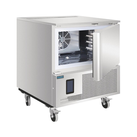
- Page 3 Product Description UA014-A - POLAR Blast Chiller with Touch screen Controller (3 x 1/1GN) UA015-A - POLAR Blast Chiller with Touch screen Controller (5 x 1/1GN) UA016-A - POLAR Blast Chiller with Touch screen Controller (10 x 1/1GN) Introduction Please take a few moments to carefully read through this manual.
- Page 4 Telephone Helpline: 1300225960 Pack Contents • It is recommended that metal containers / trays are used as other materials such as The following is included: plastic or polystyrene containers will act as an • POLAR Blast Chiller insulator and extend blast chilling times. •...
- Page 5 Telephone Helpline: 1300225960 User interface Note: If the power supply has been cut off long enough to cause a clock error (RTC code), it will be necessary to reset the Initial information date and time. The date and time can be set from the settings screen (For details, The interface has the following operating modes: please see “Section 12.1”...
- Page 6 Telephone Helpline: 1300225960 Selecting the operating mode The operating functions can be accessed from the Home screen by selecting the desired area. Note: For the use of the appliance, please follow the screen indications for instant operations. Or alternatively you can refer to the controller manual supplier with the appliance for details.
- Page 7 Telephone Helpline: 1300225960 Cleaning, Care & Maintenance Switch off and disconnect from the power supply before cleaning. • Clean the interior of the appliance as often as possible. • Do not use abrasive cleaning agents. These can leave harmful residues. •...
- Page 8 Telephone Helpline: 1300225960 Cleaning the evaporator • Clean the evaporator periodically. • As the fins of the evaporator are very sharp. Always wear protective gloves. • Only a brush can be used for cleaning. Do not use jets of liquid or sharp instruments. •...
- Page 9 Telephone Helpline: 1300225960 Troubleshooting If your POLAR appliance develops a fault, please check the following table before making a call to the Helpline or your POLAR dealer. Fault Probable Cause Solution The appliance is not The unit is not switched on Check the unit is plugged in correctly and working switched on...
- Page 10 Technical Specifications Weight Temperature Dimensions Model Voltage Power Capacity Refrigerant (kg) range H x W x D UA014-A 220-240V~ 700W 3 x GN1/1 +5°C ~ -35°C R290 965 x 804 x 826 50Hz UA015-A 220-240V~ 720W 5 x GN1/1 +5°C ~ -35°C...
- Page 11 Telephone Helpline: 1300225960 Electrical Wiring The plug is to be connected to a suitable mains socket. POLAR appliances are wired as follows: • Live wire (coloured brown) to terminal marked L • Neutral wire (coloured blue) to terminal marked N •...
- Page 12 DECLARATION OF CONFORMITY • Conformiteitsverklaring • Déclaration de conformité • Konformitätserklärung • Dichiarazione di conformità • • Declaración de conformidad • Declaração de conformidade Equipment Type • Uitrustingstype • Type d'équipement • Gerätetyp Model • Modèle • Modell • Modello •...
- Page 13 UA014-A_UA015-A_UA016-A_A5_v1_20200902.indb 13 UA014-A_UA015-A_UA016-A_A5_v1_20200902.indb 13 2020/9/2 10:10 2020/9/2 10:10...
- Page 14 UA014-A_UA015-A_UA016-A_A5_v1_20200902.indb 14 UA014-A_UA015-A_UA016-A_A5_v1_20200902.indb 14 2020/9/2 10:10 2020/9/2 10:10...
- Page 15 UA014-A_UA015-A_UA016-A_A5_v1_20200902.indb 15 UA014-A_UA015-A_UA016-A_A5_v1_20200902.indb 15 2020/9/2 10:10 2020/9/2 10:10...
- Page 16 http://www.polar-refrigerator.com/ UA014-A_UA015-A_UA016-A_A5_v1_20200902 UA014-A_UA015-A_UA016-A_A5_v1_20200902.indb 16 UA014-A_UA015-A_UA016-A_A5_v1_20200902.indb 16 2020/9/2 10:10 2020/9/2 10:10...
- Page 17 EVCO S.p.A. Vcolor 869 | Installer manual ver. 1.0 | Code 144VC869E104 Vcolor 869 Controllers for blast chillers with customizable graphical skin ENGLISH INSTALLER MANUAL ver. 1.0 CODE 144VC869E04 page 1 of 92...
- Page 18 EVCO S.p.A. Vcolor 869 | Installer manual ver. 1.0 | Code 144VC869E104 Important Read this document carefully before installation and before using the device and take all the prescribed precautions. Keep this document with the device for future consultation. Only use the device in the ways described in this document. Do not use the device as safety device. The following symbols are used in this document: indicates a suggestion indicates a warning.
-
Page 19: Table Of Contents
EVCO S.p.A. Vcolor 869 | Installer manual ver. 1.0 | Code 144VC869E104 Index INTRODUCTION ........................... 6 Introduction ............................6 Main features of the models available ..................... 7 DESCRIPTION ............................ 10 User interface description ........................10 Control module description ........................12 MEASUREMENTS AND INSTALLATION .................... - Page 20 EVCO S.p.A. Vcolor 869 | Installer manual ver. 1.0 | Code 144VC869E104 Fish sanitation ........................... 38 Thawing ............................40 Defrosting ............................42 Ice cream hardening........................... 43 Cabinet sterilisation ..........................44 Heating the needle probe ........................45 Drying .............................. 45 Retarding proofing ..........................46 8.8.1 Description of retarding proofing ....................
- Page 21 EVCO S.p.A. Vcolor 869 | Installer manual ver. 1.0 | Code 144VC869E104 ALARMS ............................79 16.1 Alarms ............................79 16.2 HACCP alarms ..........................84 ACCESSORIES ........................... 85 17.1 EVC20P52N9XXX10 - Multi-functional module ..................85 17.2 ECTSFD004 - 230 VAC/12 VAC 20 VA safety transformer ..............85 17.3 EVIF20SUXI - Non-optoisolated RS-485/USB serial interface ...............
-
Page 22: Introduction
EVCO S.p.A. Vcolor 869 | Installer manual ver. 1.0 | Code 144VC869E104 1 INTRODUCTION 1.1 Introduction Vcolor 869 manages all the most up-to-date functions of state-of-the-art blast chillers. Besides the traditional blast-chilling and blast-freezing cycles, temperature and time controlled with hard/soft function, the controller can manage up to 12 special cycles, 4 types of combined cycles, as well as the needle insertion test (including multipoint needle probes). -
Page 23: Main Features Of The Models Available
EVCO S.p.A. Vcolor 869 | Installer manual ver. 1.0 | Code 144VC869E104 1.2 Main features of the models available La seguente tabella illustra le caratteristiche principali dei modelli disponibili e i codici di acquisto. AVAILABLE MODELS/KITS OPTIONS Vcolor 869M Vcolor 869L Speed MAIN FEATURES Expansion module... - Page 24 EVCO S.p.A. Vcolor 869 | Installer manual ver. 1.0 | Code 144VC869E104 AVAILABLE MODELS/KITS OPTIONS Vcolor 869M Vcolor 869L Speed MAIN FEATURES Expansion module EVlink Wi-Fi (5") (7") regulator EVCMC869P9E EVCLC869P9E EVC20P52N9XXX10 EVDFAN1 EVIF25SWX Digital outputs electro-mechanical relays; A res. @ 250 VAC (configurable) compressor 30 A...
- Page 25 EVCO S.p.A. Vcolor 869 | Installer manual ver. 1.0 | Code 144VC869E104 AVAILABLE MODELS/KITS OPTIONS Vcolor 869M Vcolor 869L Speed MAIN FEATURES Expansion module EVlink Wi-Fi (5") (7") regulator EVCMC869P9E EVCLC869P9E EVC20P52N9XXX10 EVDFAN1 EVIF25SWX Other features clock • • • alarm buzzer •...
-
Page 26: Description
EVCO S.p.A. Vcolor 869 | Installer manual ver. 1.0 | Code 144VC869E104 2 DESCRIPTION User interface description The diagram below shows the front view of the user interface in the vertical format PART DESCRIPTION display page 10 of 92... - Page 27 EVCO S.p.A. Vcolor 869 | Installer manual ver. 1.0 | Code 144VC869E104 The diagram below shows the intended use of the user interface connectors. PART DESCRIPTION USB port RS-485 MODBUS port dip switch for the termination resistor for the RS-485 MODBUS port power supply for the user interface and connection between the user interface and the control module dip switch for the resistor connecting the user interface and the control module appliance earthing...
-
Page 28: Control Module Description
EVCO S.p.A. Vcolor 869 | Installer manual ver. 1.0 | Code 144VC869E104 2.2 Control module description The diagram below shows the intended use of the control module connectors. PART DESCRIPTION control module power supply evaporator fan and condenser fan relay defrost relay compressor relay door heater relay... -
Page 29: Measurements And Installation
EVCO S.p.A. Vcolor 869 | Installer manual ver. 1.0 | Code 144VC869E104 3 MEASUREMENTS AND INSTALLATION 3.1 Vcolor 869M user interface measurements The picture below shows the measurements of the 5-inch user interface; measurements are expressed in mm (inches). 3.2 Vcolor 869L user interface measurements The picture below shows the measurements of the 7-inch user interface;... -
Page 30: Control Module Measurements
EVCO S.p.A. Vcolor 869 | Installer manual ver. 1.0 | Code 144VC869E104 3.3 Control module measurements The picture below shows the measurements of the Vcolor 819 control module; measurements are expressed in mm (inches). Multi-functional module measurements The picture below shows the measurements of the Vcolor 819 multi-functional module; measurements are expressed in mm (inches). -
Page 31: User Interface Installation
EVCO S.p.A. Vcolor 869 | Installer manual ver. 1.0 | Code 144VC869E104 User interface installation Mounting of 7"interfaces (Vcolor 869 L): - Flush-fit installation, from behind the panel using threaded studs Mounting of 5"interfaces (Vcolor 869 M): - Flush-fit installation, from behind the panel using threaded studs - From the front of the panel, with hooks page 15 of 92... -
Page 32: Control And Multi-Functional Module Installation
EVCO S.p.A. Vcolor 869 | Installer manual ver. 1.0 | Code 144VC869E104 3.6 Control and multi-functional module installation On a flat surface with spacers. 3.7 Installation precautions Ensure that the working conditions for the device (operating temperature, humidity, etc.) are within the set limits. -
Page 33: Electrical Connection
EVCO S.p.A. Vcolor 869 | Installer manual ver. 1.0 | Code 144VC869E104 4 ELECTRICAL CONNECTION 4.1 Electrical connection of Vcolor 869M The picture below shows the electrical connection of the controller with 5-inch display. page 17 of 92... - Page 34 EVCO S.p.A. Vcolor 869 | Installer manual ver. 1.0 | Code 144VC869E104 Details of EVlink Wi-Fi electrical connection page 18 of 92...
-
Page 35: Electrical Connection Of Vcolor 869L
EVCO S.p.A. Vcolor 869 | Installer manual ver. 1.0 | Code 144VC869E104 4.2 Electrical connection of Vcolor 869L The picture below shows the electrical connection of the controller with 7-inch display. page 19 of 92... -
Page 36: Precautions For Electrical Connection
EVCO S.p.A. Vcolor 869 | Installer manual ver. 1.0 | Code 144VC869E104 Details of EVlink Wi-Fi electrical connection 4.3 Precautions for electrical connection Do not use electric or pneumatic screwdrivers on the terminal blocks of the device. If the device has been moved from a cold to a warm place, the humidity may cause condensation to form inside. -
Page 37: User Interface
EVCO S.p.A. Vcolor 869 | Installer manual ver. 1.0 | Code 144VC869E104 5 USER INTERFACE 5.1 Initial information The interface has the following operating modes: “off” (no power to the device); “stand-by” (the device is powered but switched off); “on” (the device is powered, switched on and awaiting start-up of an operating cycle); “run”... - Page 38 EVCO S.p.A. Vcolor 869 | Installer manual ver. 1.0 | Code 144VC869E104 Once loading is complete, the device will display the mode it was in before being powered down: On/Stand-by screen, press the central area to move to the Home screen; directly the Home screen.
-
Page 39: Switching The Device On And Off
EVCO S.p.A. Vcolor 869 | Installer manual ver. 1.0 ver. 1.0 | Code 144VC869E104 5.3 Switching the device on and off Switching the device on and off To switch the device on, press the central area in the To switch the device on, press the central area in the On/Stand-by screen and the Home screen will open. -
Page 40: Operation
EVCO S.p.A. Vcolor 869 | Installer manual ver. 1.0 | Code 144VC869E104 6 OPERATION 6.1 Initial information on operating cycles The device is capable of operating in the following modes: temperature controlled blast chilling and conservation hard temperature controlled blast chilling and conservation time controlled blast chilling and conservation hard time controlled blast chilling and conservation temperature controlled blast-freezing and conservation... -
Page 41: Selecting The Operating Mode
EVCO S.p.A. Vcolor 869 | Installer manual ver. 1.0 | Code 144VC869E104 6.3 Selecting the operating mode All the operating functions can be accessed from the Home screen by selecting the specific area. According to the selected machine type (see parameter E13), the Home screen menu will differ as detailed in the following table. Blast chiller Multifunction machine Makes it possible to select a cabinet pre-cooling cycle, see... -
Page 42: Blast Chilling
EVCO S.p.A. Vcolor 869 | Installer manual ver. 1.0 | Code 144VC869E104 7 BLAST CHILLING Press on this area to open the screen shown below. Now one of the areas shown can be selected: blast chilling, blast-freezing, continuous cycle and customized cycle, details below. -
Page 43: Blast Chilling/Blast-Freezing And Conservation
EVCO S.p.A. Vcolor 869 | Installer manual ver. 1.0 ver. 1.0 | Code 144VC869E104 7.1 Blast chilling/blast Blast chilling/blast-freezing and conservation freezing and conservation Pressing on one of these areas enables a blast chilling or blast Pressing on one of these areas enables a blast chilling or blast-freezing cycle to be set. The following screen opens and freezing cycle to be set. - Page 44 EVCO S.p.A. Vcolor 869 | Installer manual ver. 1.0 | Code 144VC869E104 Se il ciclo è a temperatura, viene eseguito il test per verificare il corretto inserimento della sonda spillone nell’alimento da abbattere. Se il test non viene superato, il ciclo si commuta automaticamente sulla modalità a tempo: il buzzer emette un suono e sul display viene visualizzato il simbolo di allarme in corso.
-
Page 45: Combined Cycle With Slow Cooking
EVCO S.p.A. Vcolor 869 | Installer manual ver. 1.0 | Code 144VC869E104 7.1.1 Combined cycle with slow cooking When setting a manual blast chilling/freezing cycle, if available in the machine configuration a slow cooking cycle can be added after a blast chilling/freezing. In the lower part of the screen, two dedicated areas make it possible to add a slow cooking phase or a slow cooking + holding phase. -
Page 46: Continuous Cycle
EVCO S.p.A. Vcolor 869 | Installer manual ver. 1.0 | Code 144VC869E104 Once the phase is complete, the controller moves on automatically to the next one. The end of the first two phases is signalled by the buzzer sounding. It is also possible to select the time controlled mode for this cycle, in which case the controller moves on to the next phase when the set time has elapsed. -
Page 47: Multi-Timer Mode
EVCO S.p.A. Vcolor 869 | Installer manual ver. 1.0 | Code 144VC869E104 7.3.2 Multi-timer mode The time controlled cycle makes it possible to set up to four timers. The cycle starts up activating only the first timer with its pre-set values. The other timers and their pre-set values can be enabled by pressing the pencil icon and setting a time once the cycle is underway. -
Page 48: Customized Cycle
EVCO S.p.A. Vcolor 869 | Installer manual ver. 1.0 | Code 144VC869E104 7.4 Customized cycle The customized mode makes it possible to set up a cycle consisting of a maximum of 4 phases (3 blast chilling and 1 conservation) and these can be temperature or time controlled or a mixture of both. The customized cycle starts up and activates the first phase, which by default is a needle probe phase. -
Page 49: Setting The Set Points
EVCO S.p.A. Vcolor 869 | Installer manual ver. 1.0 | Code 144VC869E104 7.5 Setting the set points 7.5.1 Setting the cabinet temperature set point When selecting a continuous or customized blast chilling or blast-freezing cycle, the pre-set cabinet temperature, product temperature, time and fan speed values when the parameters were set are loaded. These can be modified by the user within the permitted range for the parameters. -
Page 50: Running The Cycle
EVCO S.p.A. Vcolor 869 | Installer manual ver. 1.0 | Code 144VC869E104 Running the cycle Pressing the key starts up the cycle as it has been set. If it is a temperature controlled cycle, the blast chilling/blast-freezing phases terminate when the needle probe, or probes, reach the set temperature. If it is a time controlled cycle, the blast chilling/blast-freezing phases terminate when the set time period, or periods, have elapsed. -
Page 51: Recording Historical Data
EVCO S.p.A. Vcolor 869 | Installer manual ver. 1.0 | Code 144VC869E104 The sensor showing the highest temperature is then used as the reference point for the end of the temperature controlled cycles. Any sensors for which the test is not completed with a successful outcome are not subsequently used. If the test fails to record a positive outcome, that is to say the needle probe is not inserted, the buzzer sounds and the cycle automatically changes to time-controlled or keeps on as a temperature-based cycle, depending on how parameter E14 is set. - Page 52 EVCO S.p.A. Vcolor 869 | Installer manual ver. 1.0 | Code 144VC869E104 At the end of a time controlled cycle, the initial screen for the blast chilling/blast-freezing modes will appear. page 36 of 92...
-
Page 53: Special Cycles
EVCO S.p.A. Vcolor 869 | Installer manual ver. 1.0 | Code 144VC869E104 SPECIAL CYCLES Press this area on the Home page to open the screen shown below. This screen grants access to further functions, some always present, others that can be activated by setting the parameter. -
Page 54: Fish Sanitation
EVCO S.p.A. Vcolor 869 | Installer manual ver. 1.0 | Code 144VC869E104 Pressing this area enables selection of a drying cycle (a function activated with the door closed); see section 8.7. Pressing this area enables selection of a proofing cycle (a function activated by parameter); see section Errore. - Page 55 EVCO S.p.A. Vcolor 869 | Installer manual ver. 1.0 | Code 144VC869E104 The sanitation cycle starts with the blast chilling phase. When the temperature recorded by the needle probe reaches the temperature to end blast chilling, the device will move on automatically to holding. The temperature to end blast chilling (set by r20) is also the working set point during holding.
-
Page 56: Thawing
EVCO S.p.A. Vcolor 869 | Installer manual ver. 1.0 | Code 144VC869E104 8.2 Thawing Pressing this area enables selection of a thawing cycle, managed according to the load of product to be thawed, in compliance with the maximum quantity stated by the manufacturer. Where possible, a slow-cooking phase or a slow cooking + holding phase can be combined with thawing. - Page 57 EVCO S.p.A. Vcolor 869 | Installer manual ver. 1.0 | Code 144VC869E104 set 1 = initial set point set 2 = final set point Five parameters are used to manage the ventilation, one for each phase, setting the fan speed independently of the load.
-
Page 58: Defrosting
EVCO S.p.A. Vcolor 869 | Installer manual ver. 1.0 | Code 144VC869E104 8.3 Defrosting Pressing this area enables selection of a manual defrosting cycle, which is started up by pressing area . When the cycle starts up the following page is displayed. Defrosting can also be done automatically at time intervals set by parameter d0, provided this value is not set at 0. -
Page 59: Ice Cream Hardening
EVCO S.p.A. Vcolor 869 | Installer manual ver. 1.0 | Code 144VC869E104 Defrosting finishes when the evaporator temperature is above the value of parameter d2 or if the temperature has not been reached within the required time set by parameter d3. In this case there is an alarm signal. 8.4 Ice cream hardening Pressing this area enables selection of an ice cream hardening cycle. -
Page 60: Cabinet Sterilisation
EVCO S.p.A. Vcolor 869 | Installer manual ver. 1.0 | Code 144VC869E104 8.5 Cabinet sterilisation Pressing this area enables selection of a sterilisation cycle. The cabinet door must be closed to start up a sterilisation cycle. Pressing the key starts up the sterilisation cycle. Sterilisation ends when the time set by parameter u6 has elapsed, after the key has been pressed or if the door is opened. -
Page 61: Heating The Needle Probe
EVCO S.p.A. Vcolor 869 | Installer manual ver. 1.0 | Code 144VC869E104 8.6 Heating the needle probe Pressing this area enables selection of a needle probe, or probes, heating cycle. The cycle can be run only if the door is open. -
Page 62: Retarding Proofing
EVCO S.p.A. Vcolor 869 | Installer manual ver. 1.0 | Code 144VC869E104 This is a cycle of forced-air ventilation that can be activated with the door closed and for a duration set by parameter u13. If the door is opened during drying this does not affect the cycle. The cycle stops when the prescribed time has elapsed or when the key is pressed. - Page 63 EVCO S.p.A. Vcolor 869 | Installer manual ver. 1.0 | Code 144VC869E104 A proofing cycle consists of 5 phases with different temperatures, relative humidity, fan speeds and durations, one following on from the other, as in the sequence described below. 8.8.1.1 BLOCKING phase Temperature regulation is active and has a neutral zone adjustment, the temperature setpoint, the fan speed and duration in hours and minutes for the phase are set by the end-user.
-
Page 64: Setting Up A Retarding Proofing Cycle
EVCO S.p.A. Vcolor 869 | Installer manual ver. 1.0 | Code 144VC869E104 8.8.2 Setting up a retarding proofing cycle 8.8.2.1 Starting and stopping a cycle Press the key to access to the following screen displaying all the phases making up a RETARDING-PROOFING cycle: blocking, conservation, re-awakening, proofing and baking delay The cycle starts up when the area is pressed and it terminates automatically at the end of phase 4 and... - Page 65 EVCO S.p.A. Vcolor 869 | Installer manual ver. 1.0 | Code 144VC869E104 using the special menus and once the key has been pressed, the proofing cycle starts up. It is not possible to modify the set points while the cycle is in progress. If a phase is set at 0, it will not be run. In the blast chilling phase the cabinet humidity control can be omitted using parameter rU4, but this must be set in the other phases.
-
Page 66: Slow Cooking
EVCO S.p.A. Vcolor 869 | Installer manual ver. 1.0 | Code 144VC869E104 Alternatively, the cycle end date can be postponed using the quick key. 8.9 Slow cooking Pressing this area enables selection of a slow cooking cycle, which can consist of two phases. This function can only be enabled if an expansion has been set (see parameter E12). - Page 67 EVCO S.p.A. Vcolor 869 | Installer manual ver. 1.0 | Code 144VC869E104 fan speed Two areas at the bottom of the screen make it possible to add a subsequent blast chilling/blast-freezing phase and a product holding/conservation phase For blast chilling or blast-freezing, the pre-settings are those for the cycle, whereas the following parameters are used to set up a holding or conservation phase: rH13 cabinet set point for holding phase...
-
Page 68: Conservation
EVCO S.p.A. Vcolor 869 | Installer manual ver. 1.0 | Code 144VC869E104 8.10 Conservation Press this area to select a conservation in cooling, heating or neutral zone mode. The presettings of the cooling cycle are those of the blast-chilling, while the presettings of heating and neutral zone cycles are those of slow cooking. -
Page 69: Recipe Book
EVCO S.p.A. Vcolor 869 | Installer manual ver. 1.0 ver. 1.0 | Code 144VC869E104 9 RECIPE BOOK The controller has two types of recipe book The controller has two types of recipe book: "Cookbook" and "My Cookbook". 9.1 "COOKBOOK" recipe book recipe book It is an area mainly dedicated to OEM, who It is an area mainly dedicated to OEM, who need full autonomy when personalizing the recipe books for their... -
Page 70: My Cookbook" Recipe Book
EVCO S.p.A. Vcolor 869 | Installer manual ver. 1.0 | Code 144VC869E104 9.2 "MY COOKBOOK" recipe book It is an area dedicated to the final customer. It is possible to save up to 40 recipes using the Western alphabet and without translation. - Page 71 EVCO S.p.A. Vcolor 869 | Installer manual ver. 1.0 | Code 144VC869E104 Scroll the page and select the desired position where to save a new recipe or overwrite an existing one; Press to confirm : the alphabetic keyboard is now accessible (press to exit the procedure without saving);...
-
Page 72: Starting "My Cookbook" Recipes
EVCO S.p.A. Vcolor 869 | Installer manual ver. 1.0 | Code 144VC869E104 9.2.2 Starting “MY COOKBOOK” recipes To start a recipe, operate as follows: Make sure the device is on and no procedure is underway;. Touch the Enter the menu and select the desired recipe In the "Cycle Summary"... -
Page 73: Pre-Cooling
EVCO S.p.A. Vcolor 869 | Installer manual ver. 1.0 | Code 144VC869E104 PRE-COOLING Pressing this area on the Home page enables selection of a pre-cooling cycle. This cycle is similar to a normal blast chilling cycle and it may precede all operating cycles. Pressing the area in question opens the following screen. -
Page 74: Adjustments
EVCO S.p.A. Vcolor 869 | Installer manual ver. 1.0 | Code 144VC869E104 ADJUSTMENTS 11.1 Door frame heating output This function is only available if one of the relays is configured as door frame heating. This function is activated automatically when the board is in “on” or “run” mode and the cabinet temperature falls below the value set by parameter u5 minus the fixed hysteresis of 2°C (4°F). -
Page 75: Gestione Secondo Compressore
EVCO S.p.A. Vcolor 869 | Installer manual ver. 1.0 ver. 1.0 | Code 144VC869E104 11.3 Gestione secondo compressore Gestione secondo compressore If one of the realy outputs is configured as second is configured as second compressor, compressor 1 and 2 are managed as follows are managed as follows: When regulating with 2 compressors, the differential When regulating with 2 compressors, the differential set by parameter r0 will be halved... - Page 76 EVCO S.p.A. Vcolor 869 | Installer manual ver. 1.0 | Code 144VC869E104 The values obtained this way shall be set for F19 and F20 respectively.. The evaporator fan management differs according to the cycle in use, as specified below. The way the evaporator fan is managed changes depending on the presence of the evaporator probe, which is enabled setting parameter P4 to 1.
-
Page 77: Condenser Fan Management
EVCO S.p.A. Vcolor 869 | Installer manual ver. 1.0 | Code 144VC869E104 11.6 Condenser fan management This function is only available if one of the relays is configured as condenser fan. The management mode of condenser fans varies according to whether the condenser probe is present, which can be enabled by setting parameter P5 to 1. -
Page 78: Thawing Heater Management
EVCO S.p.A. Vcolor 869 | Installer manual ver. 1.0 | Code 144VC869E104 The defrost output will be activated regardless of the value of parameter d1 for the entire duration of the defrost. 11.11 Thawing heater management This function is only available if one of the relays is configured as thawing. These are activated during thawing to bring the cabinet temperature to the set point value. -
Page 79: Settings
EVCO S.p.A. Vcolor 869 | Installer manual ver. 1.0 | Code 144VC869E104 SETTINGS 12.4 Select language The SETTINGS are accessed by pressing area Press this area to select the desired language among the Home page. The page displays the following menu: the pre-set ones. -
Page 80: Using The Usb Port
EVCO S.p.A. Vcolor 869 | Installer manual ver. 1.0 | Code 144VC869E104 USING THE USB PORT 13.1 Initial information The USB port makes possible the following operations. upload and download settings of “MY COOKBOOK” recipes and of “Special cycles” working cycles (hereinafter referred to as “programs”);... -
Page 81: Downloading Configuration Parameter Settings (Controller -> Usb)
EVCO S.p.A. Vcolor 869 | Installer manual ver. 1.0 | Code 144VC869E104 13.1.4 Downloading configuration parameter settings (controller -> USB) To download the settings of the configuration parameter, operate as follows: Make sure the device is in stand-by and no procedure is underway; Insert the USB flash drive into the USB port and wait until the menu is displayed;... -
Page 82: Epoca Cloud Platform
EVCO S.p.A. Vcolor 869 | Installer manual ver. 1.0 | Code 144VC869E104 EPOCA CLOUD PLATFORM EPoCA is a remote monitoring system based on a cloud platform. All that is needed is a simple onsite Wi-Fi internet connection to enable the controller, using EVlink Wi-Fi module, to connect to the cloud system, making it possible to remotely manage equipment from a PC, tablet or smartphone. -
Page 83: List Of Configuration Parameters
EVCO S.p.A. Vcolor 869 | Installer manual ver. 1.0 | Code 144VC869E104 LIST OF CONFIGURATION PARAMETERS The following table gives the meaning of the configuration parameters. N.B. Because some functions are managed according to the value set for some parameters, ensure these are set correctly and consistently. - Page 84 EVCO S.p.A. Vcolor 869 | Installer manual ver. 1.0 | Code 144VC869E104 PAR. DEFAULT MIN. MAX. U.M. MAIN REGULATOR Cabinet set point differential in blast chilling, blast-freezing, °C/°F sanitation, ice cream hardening and customized cycles. Duration of time controlled blast chilling Duration of time controlled blast-freezing Product temperature to end temperature controlled blast chilling °C/°F...
- Page 85 EVCO S.p.A. Vcolor 869 | Installer manual ver. 1.0 | Code 144VC869E104 Product temperature set point for the first phase of sanitation °C/°F and cabinet temperature set point for the second phase of sanitation. Duration of second sanitation phase. °C/°F Cabinet temperature set point for the third phase of sanitation.
- Page 86 EVCO S.p.A. Vcolor 869 | Installer manual ver. 1.0 | Code 144VC869E104 °C/°F Cabinet temperature set point for proofing phase. °C/°F Cabinet temperature set point for holding phase. °C/°F Neutral zone relative threshold (heating) for all proofing phases. Blast chilling phase duration (for proofing cycle). Re-awakening phase duration.
- Page 87 EVCO S.p.A. Vcolor 869 | Installer manual ver. 1.0 | Code 144VC869E104 Pre-set % humidifying during proofing Pre-set % humidifying during holding rU10 Pre-set % humidifying during slow cooking. rU11 Pre-set % humidifying during holding after slow cooking. PAR. DEFAULT MIN.
- Page 88 EVCO S.p.A. Vcolor 869 | Installer manual ver. 1.0 | Code 144VC869E104 parameter i0 is set to a value other than 0). Evaporator temperature to end defrosting. See also parameter °C/°F If the evaporator probe is not present (P4=0), it sets the defrost duration.
- Page 89 EVCO S.p.A. Vcolor 869 | Installer manual ver. 1.0 | Code 144VC869E104 Power failure duration sufficient for the power failure alarm to be saved (“POWER FAILURE” code) when this is restored = the alarm will not be signalled °C/°F Parameter A1 and A4 differential Duration of buzzer activation on completion of blast chilling and blast-freezing.
- Page 90 EVCO S.p.A. Vcolor 869 | Installer manual ver. 1.0 | Code 144VC869E104 - - - - Fan speed in first sanitation phase (blast chilling). - - - - Fan speed in second sanitation phase (holding). - - - - Fan speed in third sanitation phase (conservation). - - - - Fan speed during customized blast chilling.
- Page 91 EVCO S.p.A. Vcolor 869 | Installer manual ver. 1.0 | Code 144VC869E104 PAR. DEFAULT MIN. MAX. U.M. DIGITAL INPUTS Effect caused by the door opening, or when the door switch input is activated. = no effect and no signal = the compressor, evaporator fan, thawing heater, heater and humidifier are switched off and the cabinet light is on, once the time set by parameter i2 has elapsed, the - - - -...
- Page 92 EVCO S.p.A. Vcolor 869 | Installer manual ver. 1.0 | Code 144VC869E104 Function managed by output K1 Unused Compressor 1 Compressor 2 Defrost Evaporator fan Condenser fan Door heater u01c - - - - Thawing heater Alarm Pump down valve 10.
- Page 93 EVCO S.p.A. Vcolor 869 | Installer manual ver. 1.0 | Code 144VC869E104 Temperature to end needle probe heating. See also parameter °C/°F Maximum duration of needle probe heating. See also parameter u7 0 = needle probe heating is disabled. - - - - unused Enable evaporator ventilation during sterilisation - - - -...
- Page 94 EVCO S.p.A. Vcolor 869 | Installer manual ver. 1.0 | Code 144VC869E104 Time-out for keypad lock Display EVCO splash screen when power is restored - - - - = no = yes Enable expansion module functions 0 = no 1 = only slow cooking - - - - 2 = only retarding proofing 3 = slow cooking + retarding proofing...
-
Page 95: Alarms
EVCO S.p.A. Vcolor 869 | Installer manual ver. 1.0 | Code 144VC869E104 ALARMS 16.1 Alarms The table below lists the various alarms. Code Meaning Clock error. To correct Re-set the date and time. Main consequences The device will not memorise the date and time an HACCP alarm happened. The alarm output will be activated. - Page 96 EVCO S.p.A. Vcolor 869 | Installer manual ver. 1.0 | Code 144VC869E104 Condenser probe error. To correct The same as for the cabinet probe error but with reference to the condenser probe. Main consequences CONDENSER PROBE The condenser fan will operate in parallel with the compressor. The condenser overheat alarm will never be activated.
- Page 97 EVCO S.p.A. Vcolor 869 | Installer manual ver. 1.0 | Code 144VC869E104 High pressure alarm. To correct Check the state of the high pressure input. HIGH PRESSURE Check the value of parameter i6. SWITCH Main consequences If the cycle underway requires use of the compressor, the cycle will be interrupted. The alarm output will be activated.
- Page 98 EVCO S.p.A. Vcolor 869 | Installer manual ver. 1.0 | Code 144VC869E104 User interface-control module communication error. To correct BOARD COMMUNICATIO Check the user interface-control module connection. Main consequences Any cycle underway will be terminated and it will not be possible to start one up. User interface-control module compatibility error.
- Page 99 EVCO S.p.A. Vcolor 869 | Installer manual ver. 1.0 | Code 144VC869E104 Compressor locked alarm. To correct Check the condenser temperature Check the value of parameter C7 COMPRESSOR Disconnect the device from the power supply and clean the condenser. LOCKED Main consequences If the error happens during “stand-by”, it will not be possible to select or start up an operating cycle.
-
Page 100: Haccp Alarms
EVCO S.p.A. Vcolor 869 | Installer manual ver. 1.0 | Code 144VC869E104 16.2 HACCP alarms To access the HACCP alarm area, press area in the Home screen. The screen below will be displayed. The following HACCP alarms are listed. Blast chilling/blast-freezing cycle duration Power failure Door open High temperature alarm... -
Page 101: Accessories
EVCO S.p.A. Vcolor 869 | Installer manual ver. 1.0 | Code 144VC869E104 ACCESSORIES 17.1 EVC20P52N9XXX10 - Multi-functional module The module makes it possible to add to the controller’s potential functions, enabling special cycles to be managed with control of heating and steam generation and injection. 17.2 ECTSFD004 VAC/12... -
Page 102: 0812000002 - Usb Plug For Panel Installation
EVCO S.p.A. Vcolor 869 | Installer manual ver. 1.0 | Code 144VC869E104 17.4 0812000002 - USB plug for panel installation This plug makes the controller’s USB port more accessible. To connect the plug to the USB port, connecting cable 0810500018 or 0810500020 must be used (to be ordered separately). -
Page 103: Evusb4096M - 4Gb Usb Flash Drive
EVCO S.p.A. Vcolor 869 | Installer manual ver. 1.0 | Code 144VC869E104 17.7 EVUSB4096M - 4GB USB flash drive This flash drive makes it possible to upload and download the controller configuration and the customized cycles saved by the user. HACCP data can also be exported in CSV format. 17.8 EVIF25SWX –... -
Page 104: Technical Specifications
EVCO S.p.A. Vcolor 869 | Installer manual ver. 1.0 | Code 144VC869E104 TECHNICAL SPECIFICATIONS 18.1 Technical specifications Purpose of the control device Function controller. Construction of the control device Built-in electronic device. user interface control module Container Open frame board behind glass. Open frame board. - Page 105 EVCO S.p.A. Vcolor 869 | Installer manual ver. 1.0 | Code 144VC869E104 RoHS 2011/65/EC Environmental standards WEEE 2012/19/EU REACH (EC) Regulation no. 1907/2006. EN 60730-1 EMC standards IEC 60730-1. user interface control module Vcolor 869M (5"): powered by the control module. Power supply 115...
- Page 106 EVCO S.p.A. Vcolor 869 | Installer manual ver. 1.0 | Code 144VC869E104 9, electro-mechanical relays The maximum permitted current on loads 3 and 4 is 10 A, on load K1 is 20 A (see the electrical circuit diagram). The relays do not manage LED and fluorescent lamps Compressor relay: 30 A SPST res.
- Page 107 EVCO S.p.A. Vcolor 869 | Installer manual ver. 1.0 | Code 144VC869E104 Vcolor 869 Controller for blast chillers with customizable graphical skin Installer manual ver. 1.0 GA - 11/20 Code 144VC869E104 This document is the exclusive property of EVCO and any reproduction or disclosure is absolutely prohibited unless expressly authorised by EVCO.
- Page 108 EVCO S.p.A. Vcolor 869 | Installer manual ver. 1.0 | Code 144VC869E104 EVCO S.p.A. Via Feltre 81, 32036 Sedico Belluno ITALIA Tel. 0437 / 8422 Fax 0437 / 83648 info@evco.it www.evco.it page 92 of 92...
Need help?
Do you have a question about the UA014-A and is the answer not in the manual?
Questions and answers