
Related Manuals for ADITIVA 3D ENDER 3 CONVEYOR 90 KIT

Summary of Contents for ADITIVA 3D ENDER 3 CONVEYOR 90 KIT
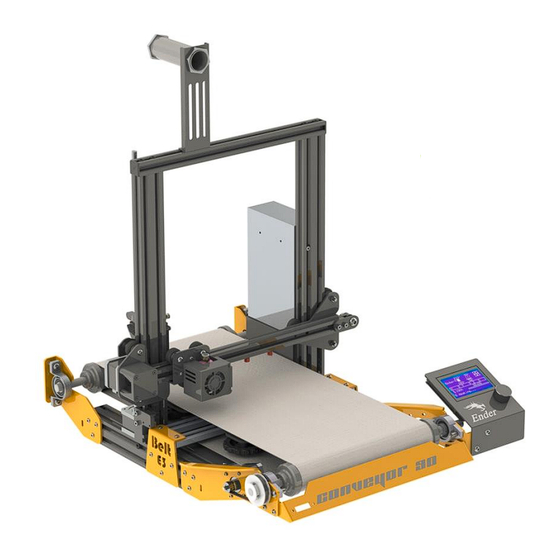
- Page 1 P a g e 1 | 26 Ender 3 Conveyor 90 Belt Kit assembly manual www.belt3dprinterkit.com...
-
Page 2: Table Of Contents
Content Chapter 1 Intro Step 1.1 What is included in this kit? Step 1.2 Needed tools Chapter 2 Disassembling ENDER 3 Step 2.1 Removing screen Step 2.2 Y axis and heatbed assembly Step 2.3 Remove back endcaps Chapter 3 Preparing frame Step 3.1 Installing bottom plates Chapter 4 Installing Belt and Heatbed system... -
Page 3: Chapter 1 Intro
Chapter 1 Intro What is included in this kit? Step 1.1 In this kit you will find all the necessary parts for converting your regular Ender 3/PRO/V2 3d printer models into a sequential Belt 3d printer. Parts lists are indicated on each step for better understanding and guidance. -
Page 4: Step 2.2 Y Axis And Heatbed Assembly
Remove cable from the back of the screen, please be aware of the connector position, since it will be connected later. Figure 2 disconnecting screen Using an Allen key, remove 2 x m5 screws that holds screen in place. ... -
Page 5: Step 2.3 Remove Back Endcaps
Figure 4 Removing Y axis and heatbed Remove back endcaps Step 2.3 Please be sure to remove back endcaps of the 4040 aluminum bars from the bottom frame. Figure 5 Removing back endcaps P a g e 5 | 26 Ender 3 Conveyor 90 Belt Kit assembly manual www.belt3dprinterkit.com... -
Page 6: Chapter 3 Preparing Frame
Chapter 3 Preparing frame Installing bottom plates Step 3.1 Figure 6: P1 C90 BACK LEFT BRACKET Figure 7: P2 C90 BACK RIGHT BRACKET Figure 8: P3 C90 FRONT LEFT BRACKET P a g e 6 | 26 Ender 3 Conveyor 90 Belt Kit assembly manual www.belt3dprinterkit.com... - Page 7 Figure 9: P4 C90 FRONT RIGHT BRACKET Next items from the KIT: ITEM ITEM DESCRIPTION Quantity Type P1 C90 BACK LEFT BRACKET P2 C90 BACK RIGHT BRACKET P3 C90 FRONT LEFT BRACKET P4 C90 FRONT RIGHT BRACKET M4 x 8 mm Screw M4 T-Slot nut ...
- Page 8 Figure 11: Use holes on each bracket to align with bottom frame P a g e 8 | 26 Ender 3 Conveyor 90 Belt Kit assembly manual www.belt3dprinterkit.com...
-
Page 9: Chapter 4 Installing Belt And Heatbed System
Chapter 4 Installing Belt and Heatbed system Figure 12 Belt system Assembly Preparing rollers Step 4.1 Next items from the KIT will be used: ITEM ITEM DESCRIPTION Quantity Type Roller BODY 40 mm 12 mm ROD Roller Cap 46mm M4x8mm Black Headless screw ... -
Page 10: Step 4.2 Installing Rollers And Belt
Figure 13 Roller assembly components 50 mm 50 mm Figure 14 Rod is centered with roller body Installing Rollers and Belt Step 4.2 Next items from the KIT will be used: ITEM ITEM DESCRIPTION Quantity Type Roller Assembly FLANGE BEARING 12mm BLOCK BEARING 12mm M6x18mm SCREW M6x30mm SCREW... - Page 11 Insert Block Bearing 12mm on both sides of the other Roller: FRONT ROLLER MOUNT: Take the ROLLER with FLANGE BEARINGS on it, install it with M6x18 SCREWS and M6 NYLOCK NUTS, please be aware in this step belt have to be inserted as shown in the next picture.
- Page 12 REAR ROLLER MOUNT: Take the ROLLER with BLOCK BEARINGS on it, install it with M6x30 SCREWS and M6 NYLOCK NUTS, please be aware in this step belt have to be inserted as shown in the next picture, DO NOT ADJUST SCREWS YET, JUST INSTALL SCREWS ON BOTH SIDES: ROLLER HAS TO BE CENTERED! ...
- Page 13 Figure 16 Measuring axles on right side Figure 17 Measuring axles on left side Belt motor installation: On the LEFT FRONT side of machine, take the Timing Pulley 60T, bore 12mm GT2 and insert it on the end of the REAR ROLLER, then using the original Y motor and pulley (using M4x8mm Screws and M4 slot nuts), proceed to install it.
-
Page 14: Step 4.3 Installing Heatbed
Figure 18 Belt motor assembly Installing Heatbed Step 4.3 Next items from the KIT will be used: ITEM ITEM DESCRIPTION Quantity Type Original Heatbed with base plate Original Part and leveling nuts and springs Heatbed mount plate 1020 ALU PROFILE 326mm M4x8 mm SCREW M4 Slot nut M5x8 mm SCREW... - Page 15 Figure 19 Heatbed base plate without wheels and showing aligned holes pairs. Installing support bars for heatbed: Using 1020 ALU PROFILE 326mm and M5x8 Screw (04) and M5 Slot Nuts (04), fix the heated base plate with the mentioned bars, as shown in the next picture: Note: You might end up with a 90°...
-
Page 16: Chapter 5 Finishing Installation
Proceed to insert Heated bed with support alu bars assembled, from the left side of machine right under the tensioned BELT. (cable of heatbed will come out from the left side to the machine and going to the electronic box) Figure 21 Heatbed must be inserted inside belt ... -
Page 17: Step 5.2 Face Plate Mounting
Figure 22 Install back Screen into right position Face plate mounting Step 5.2 Install provided face plate into the front of the machine, using 4 M4x16 screws and M4 nylock nuts: Figure 23 Install face plate, keeping a gap of 2mm from the belt Chapter 6 Electronics and firmware Electronics Step 6.1... -
Page 18: Step 6.2 Firmware
Endstops: X and Z axis only have endstops, belt system doesn’t need one. Z Endstop Installation: Using Z endstop assemble it with original bracket, and then install it using a M4x8mm Screw and Slot nut, just cut bracket tab in order to let endstop to go lower: Figure 24 Cut Z endstop bracket tab ... - Page 19 Figure 25 leveling bed left side Figure 26 leveling bed right side Z endstop Regulation: loosen Z endstop support, get X axis down to bed, place a piece of paper between nozzle and belt, then push endstop back to X axis until switch is pressed down finally adjust endstop support.
- Page 20 Chapter 8 Slicing Simplify slicer settings Step 8.1 On this thread we will find how to do multi-process in order to do sequential printing for multiple parts printing on Simplify 3D. Import provided FFF profile P a g e 20 | 26 Ender 3 Conveyor 90 Belt Kit assembly manual www.belt3dprinterkit.com...
- Page 21 On the Processes tab, double click on the process On the FFF settings window, be sure to select Ender 3 CONVEYOR 90 profile in order to enable it. When placing the models to print, be sure them to be put one after another, separated by 250 mm distance (approximately), so when it start new print, the belt release the last print: P a g e...
- Page 22 On the Processes tab, CTRL+C and CTRL+V current Process for each part to be printed Double click the first process in order to open the settings window, once open, click on the Select model button. P a g e 22 | 26 Ender 3 Conveyor 90 Belt Kit assembly manual www.belt3dprinterkit.com...
- Page 23 Select ONLY first model to be printed, and click on OK Double click on the next process, and click on Select models again: P a g e 23 | 26 Ender 3 Conveyor 90 Belt Kit assembly manual www.belt3dprinterkit.com...
- Page 24 Select ONLY second model to be printed this time, and click OK: Repeat last 2 previous steps for each additional model Once every model has its assigned process, click on Prepare to print P a g e 24 | 26 Ender 3 Conveyor 90 Belt Kit assembly manual www.belt3dprinterkit.com...
- Page 25 A new window will show up, Select Processes for Printing, click on Select All, select Sequential printing: object-by-object, and set Max height clearance value as 250 mm Check on the Preview mode, if everything is ok, simulation will show as nozzle prints one object after another: P a g e 25 | 26...
- Page 26 Finally Save G-code to your micro SD card and print it. P a g e 26 | 26 Ender 3 Conveyor 90 Belt Kit assembly manual www.belt3dprinterkit.com...
Need help?
Do you have a question about the ENDER 3 CONVEYOR 90 KIT and is the answer not in the manual?
Questions and answers