Subscribe to Our Youtube Channel
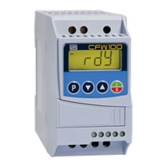
Summary of Contents for Weq CFW100
- Page 1 Motors I Automation I Energy I Transmission & Distribution I Coatings Frequency Inverter Convertidor de Frecuencia Inversor de Frequência CFW100 User's Manual Manual del Usuario Manual do Usuário...
- Page 3 User's Manual Manual del Usuario Manual do Usuário Series/Série: CFW100 English / Español / Português Document/Documento: 10001432497 / 03 Models/Modelos: Frame A, B and C Tam A, B y C Mec A, B e C Date/Fecha/Data: 03/2014...
- Page 4 P204 = 5 for 60 Hz. „ P204 = 6 for 50 Hz. „ It is only necessary to set these parameters once. Refer to the programming manual of the CFW100 for further details about the programming of parameter P204. 2 | CFW100...
-
Page 5: Table Of Contents
1.2 SAFETY WARNINGS IN THE PRODUCT ..............6 1.3 PRELIMINARY RECOMMENDATIONS ............... 6 2 GENERAL INFORMATION ....................8 2.1 ABOUT THE MANUAL ....................8 2.2 ABOUT THE CFW100 ....................8 2.3 TERMINOLOGY ......................11 2.4 IDENTIFICATION LABEL .................... 11 2.5 RECEIVING AND STORAGE ..................12 3 INSTALLATION AND CONNECTION ................ - Page 6 6.5 CLEANING INSTRUCTIONS ..................36 7 ACCESSORIES ........................38 8 TECHNICAL SPECIFICATIONS ..................39 8.1 POWER DATA ........................ 39 8.2 ELECTRONICS/GENERAL DATA ................40 8.2.1 Considered Standards ..................41 APPENDIX A - FIGURES ...................... 118 APPENDIX B – TECHNICAL SPECIFICATIONS..............120 4 | CFW100...
-
Page 7: Safety Warnings In The Manual
Safety Instructions 1 SAFETY INSTRUCTIONS This manual provides information for the proper installation and operation of the CFW100 frequency inverter. It has been written to be used by qualified personnel with suitable training or technical qualification for operating this type of equipment. The personnel shall follow all the safety instructions described in this manual and/or defined by the local regulations. -
Page 8: Safety Instructions
(fans) even after the AC power is disconnected or switched off. Wait at least ten minutes after turning off the input power for the complete discharge of the power capacitors. Always connect the grounding point of the inverter to the protection earth (PE). 6 | CFW100... - Page 9 DANGER! Connectors XCA and XCB do not present USB compatibility; therefore, they cannot be connected to USB doors. These connectors serve only as interface between the CFW100 frequency inverter and its accessories. DANGER! Les connecteurs XCA et XCB ne présentent pas de compatibilité USB, ils ne peuvent donc pas être connectés à...
- Page 10 Electronic boards have components sensitive to electrostatic discharges. Do not touch directly on components or connectors. If necessary, first touch the grounding point of the inverter, which must be connected to the protection earth (PE) or use a proper grounding strap. 8 | CFW100...
-
Page 11: General Information
It is not the intention of this manual to present all the possibilities for the application of the CFW100, as well as WEG cannot take any liability for the use of the CFW100 which is not based on this manual. - Page 12 “V/f Quadratic”, which results in energy savings. The V/f mode is used when more than a motor is activated by an inverter simultaneously (multimotor applications). The main components of the CFW100 can be viewed in the block diagram of Figure 2.1 on...
- Page 13 (remote) Flash Memory Module Control board Digital with CPU Converter inputs RS-485 USB-RS485 16 bits (DI1 to DI4) Bluetooth Bluetooth adapter Adapter CANopen/ (SUPERDRIVE DeviceNet G2, WLP) Analog input and relay output Figure 2.1: CFW100 block diagram CFW100 | 11...
-
Page 14: Terminology
I to the year) Serial number Production order WEG stock item Rated output data Rated input data (voltage, current and frequency) (voltage, current and frequency) CFW100 Side Label Figure 2.2: Description of the CFW100 identification label 12 | CFW100... -
Page 15: Receiving And Storage
Report any damage immediately to the carrier. If the CFW100 is not installed soon, store it in a clean and dry location (temperature between -25 ºC and 60 ºC (-13 ºF and 140 ºF)), with a cover to prevent dust accumulation inside it. -
Page 16: Installation And Connection
Mount the inverter in the upright position on a flat and vertical surface. Allow the minimum clearances indicated in Figure B2 on page 124, in order to allow the circulation of the cooling air. Do not install heat sensitive components right above the inverter. 14 | CFW100... -
Page 17: Cabinet Mounting
0.17 7.73 3.65 0.22 3.1.2.2 Surface Mounting Figure B2 on page 124 illustrates the CFW100 installation procedure for surface mounting, using the mounting accessory with screws (for further information, refer to chapter 7 ACCESSORIES on page 39). 3.1.2.3 DIN-Rail Mounting The CFW inverter can also be mounted directly on a 35mm-rail, in accordance with DIN EM 50.022. -
Page 18: Electrical Installation
„ applicable local regulations for electrical installations. Make sure the AC power supply is disconnected before starting the installation. „ The CFW100 must not be used as an emergency stop device. Provide other „ devices for that purpose. DANGER! Les informations suivantes constituent uniquement un guide pour une „... -
Page 19: Circuit Breakers, Fuses, Grounding And Power
NOTE! The wire gauges listed in Table B1 on page 121 are guiding values. Installation conditions and the maximum permitted voltage drop must be considered for the proper wiring sizing. CFW100 | 17... -
Page 20: Power Connections
Installation and Connection 3.2.3 Power Connections Power supply L1/L L2/N Disconnecting Fuse switch PE W V U V W PE Shield Figure 3.1: Power and grounding connections 18 | CFW100...


Need help?
Do you have a question about the CFW100 and is the answer not in the manual?
Questions and answers