Table of Contents

Related Manuals for DINKO Instruments UV/VIS 6000

Summary of Contents for DINKO Instruments UV/VIS 6000
- Page 1 DINKO User’s Manual UV/VIS 6000 INSTRUMENTS UV/VIS 6000 Ultraviolet Visible Spectrophotometer Smart Touch Screen Reference Manual Version: March 2021 Mark c/ Encarnació, 123-125 / 08024-Barcelona dinter@dinko.es www.dinko.es...
- Page 2 DINKO User’s Manual UV/VIS 6000 INSTRUMENTS Dear user: Thank you for purchasing and using the instrument of shanghai metash instrument corporation. Please read the manual carefully to enable you to know the performance of the instrument as soon as possible and to master its using method.
-
Page 3: Table Of Contents
DINKO User’s Manual UV/VIS 6000 INSTRUMENTS Contents 1. Summary .................... 5 1.1 Working Principle ..............5 1.2 Instrument Characteristics ............6 1.3 Application Field ............... 7 1.4 Technical Parameters ..............8 1.5 Symbols and Prompt Notes ............8 1.6 Brief Introduction of System and Structure ....... 9 2. - Page 4 DINKO User’s Manual UV/VIS 6000 INSTRUMENTS 3.2.2 Data processing .............. 18 3.3 Quantitative Analysis .............. 20 3.3.1 Standard curve test ............21 3.3.2 Application of coefficient method ..........29 3.3.3 Setting concentration unit .............. 31 3.4 Spectral Scanning ............... 32 3.4.1 Wavelength scan ..............
-
Page 5: Working Principle
DINKO User’s Manual UV/VIS 6000 INSTRUMENTS 3.6.6 Restoring defaults ............584 4. Routine maintenance ................ 606 5. Troubleshooting ................629 1. Summary 1.1 Working Principle The working principle of spectrophotometer is mainly based on Lambert - Bill law. When a bundle of monochromatic light passes through a uniform... -
Page 6: Instrument Characteristics
1.2 Instrument Characteristics The characteristics of UV/VIS 6000 Spectrophotometer are the following: The stray light is low and resolution is high in optical system, so the stability and reproducibility are excellent and the readings are accurate. -
Page 7: Application Field
UV/VIS 6000 is a UV spectrophotometer with touch screen. The instrument is stable, accurate and powerful and has obvious... -
Page 8: Technical Parameters
DINKO User’s Manual UV/VIS 6000 INSTRUMENTS advantages in the fields of scientific research and quality control. 1.4 Technical Parameters Type UV/VIS 6000 Wavelength range (nm) 190-1100 Spectral bandwidth (nm) 1,8 nm Wavelength accuracy (nm) ± 0.5 Wavelength repeatability ≤ 0.2 (nm) 0-200%T、-0.3-3A、0-9999C... -
Page 9: Brief Introduction Of System And Structure
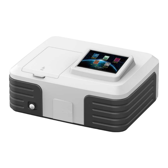
The shape and structure of the instrument is shown in figure 1: 1--Hand pull rod 2—Sample room 3--Touch screen Figure 1 The shape of UV/VIS 6000 The back of the UV/VIS 6000 instrument is shown in figure 2: 1—Power switch 2-- Power supply socket 3-- Cooling vent 4-- Printer port... -
Page 10: Installation
DINKO User’s Manual UV/VIS 6000 INSTRUMENTS Figure 2 The back of UV/VIS 6000 2. Installation Please read the contents of this chapter carefully before installation. 2.1 Unpacking Please check to make sure that the instrument external packing is intact and has no opened marks before unpacking. - Page 11 DINKO User’s Manual UV/VIS 6000 INSTRUMENTS The equipment should be placed in a dry room with temperature within the range of 15 °C to 35 °C and relative humidity less than 85%. 2) Power requirements: The rated voltage of the instrument is 220 V + 22 V AC (or 110 V + 11 V AC), the frequency is 50 Hz (or 60 Hz), and a good grounding wire should be installed.
-
Page 12: Instrument Installation
DINKO User’s Manual UV/VIS 6000 INSTRUMENTS 2.3 Instrument Installation Installation procedures of the instrument are as follows: 1) Place the instrument on a stable bench after unpacking. 2) Connect instrument power cord. If equipped with a printer, connect wiring between the instrument and printer and printer power cord. - Page 13 The instrument starts self-check after displaying the welcome interface several seconds. The lamp conversion, filter, detector, deuterium lamp, tungsten lamp, wavelength calibration, battery, system parameters and dark current are detected automatically. The self-check interface of the UV/VIS 6000 Spectrophotometer is shown in figure 4.
- Page 14 DINKO User’s Manual UV/VIS 6000 INSTRUMENTS Figure 4 The self-checking interface If the self-checking is passed successfully, the status indicator light is green. If a self-checking error occurs, the buzzer alarm will automatically happen, the status indicator light will be red, and the next self-checking content will be carried out generally.
- Page 15 The main operation interface appears after pre-warming, as shown in figure 6. Figure 6 The operation main interface Photometric analysis, quantitative analysis, wavelength scan, kinetic analysis and system settings can be realized by the UV/VIS 6000. Click the required functional modules, you can enter the corresponding operation interface.
-
Page 16: Photometric Analysis
DINKO User’s Manual UV/VIS 6000 INSTRUMENTS 3.2 Photometric Analysis At the interface of photometric analysis, the user can measure the absorbance, transmittance and energy at fixed wavelengths, and also print the measurement results. Click icon at the operation main interface to enter the interface of photometric analysis (Figure 7). - Page 17 DINKO User’s Manual UV/VIS 6000 INSTRUMENTS : used to set wavelengths. : used to calibrate 0 Abs and 100%T, and correct the blank. : used to measure and record data. : to save data. : to load and print data.
-
Page 18: Data Processing
INSTRUMENTS wavelength. Figure 8 Digital input window The wavelength input range of the UV/VIS 6000 is 190 nm~1100 nm. If the input value is out of the range, the data is considered invalid and needs to be reentered. If the input wavelength is found to be incorrect, click "... - Page 19 DINKO User’s Manual UV/VIS 6000 INSTRUMENTS Save data: click button to save data to the host, and the data is automatically saved to the USB memory if the USB memory is connected. Load data, print: click button to enter printing and loading data operations interface (Figure 9).
-
Page 20: Quantitative Analysis
DINKO User’s Manual UV/VIS 6000 INSTRUMENTS Figure 9 Photometric analysis—the operation interface of printing and loading data Once the user deletes the individual data, the clear touch button should be frozen in time (click “ ” to make it show “... -
Page 21: Standard Curve Test
DINKO User’s Manual UV/VIS 6000 INSTRUMENTS Figure 10 The main interface of instrument operation 3.3.1 Standard curve test Standard curve method is a quantitative analysis method to measure the concentration of sample by comparing the standard curve established by standard sample with known concentration. "Standard curve", that is “the standard work curve". - Page 22 Different absorbance linear ranges lead to different measurement errors. The optimum linear range of absorbance is 0.2 ~ 0.8. The curve shown by the UV/VIS 6000 instrument is that the concentration value is abscissa, and the absorbance value is ordinate, but curvilinear equation is C =K×A+B, the form is different, the sample test and the display of final results...
- Page 23 DINKO User’s Manual UV/VIS 6000 INSTRUMENTS Click button at the main interface of standard curve method to enter the interface of creating standard curves (Figure 12). Create the standard curve according to the system prompts. Figure 12 The interface of creating standard curve The procedures of standard curve test are as follows: ⑴...
- Page 24 DINKO User’s Manual UV/VIS 6000 INSTRUMENTS ⑵ Standard sample test and drawing curve Click button at the main interface of standard curve method to enter the interface of creating standard curve. First, put the standard reference solution into the optical path, click button to set 0.000 Abs.
- Page 25 DINKO User’s Manual UV/VIS 6000 INSTRUMENTS Figure 13 The display interface of standard curve When the standard sample is tested, please ensure that the corresponding sample has been placed in the light path before inputting the sample concentration. The data records are not displayed by the current measurement interface, the user...
- Page 26 DINKO User’s Manual UV/VIS 6000 INSTRUMENTS Figure 14 Standard sample data display interface ⑶ Sample test Click button to enter sample test interface at the display interface of standard sample (Figure 15). Put the blank solution into the light path and click button to deduct the absorbance of the blank solution (Set 0.000Abs).
- Page 27 DINKO User’s Manual UV/VIS 6000 INSTRUMENTS and multiple sets of data can be stored into the instrument. Save data: click button to save the data to the instrument, and the data can be saved to the USB memory automatically if the USB memory is connected.
- Page 28 DINKO User’s Manual UV/VIS 6000 INSTRUMENTS Figure 16 The interface of printing and loading data The clear touch button should be frozen in time after the individual data deletion has been finished (click icon to let it show as ) to avoid misoperation in subsequent operations.
-
Page 29: Application Of Coefficient Method
DINKO User’s Manual UV/VIS 6000 INSTRUMENTS Figure 17 Loading standard curve When the curve is saved, the sequence number increases orderly, and the new established curve is saved in the last position. The instrument can store a plurality of standard curves. - Page 30 DINKO User’s Manual UV/VIS 6000 INSTRUMENTS The coefficient method is a simple application of the standard curve method. Input the known curve parameters to determine curve equation, then test the unknown concentration samples. The formula C=K×A+B in the coefficient method is given by the system, input the curve parameters K and B to carry out the measurement.
-
Page 31: Setting Concentration Unit
DINKO User’s Manual UV/VIS 6000 INSTRUMENTS the digital inputting window appears (Figure 8). Input needed wavelength, click button, the prompt message of "wavelength shift.." appears under the screen, then the instrument reaches the specified wavelength. 3) Setting the curve parameters K and B Click the parameter K settings box at the main interface of coefficient method, the digital inputting window appear (Figure 8). -
Page 32: Spectral Scanning
DINKO User’s Manual UV/VIS 6000 INSTRUMENTS Set concentration unit at quantitative analysis interface before the quantitative analysis. Click button to enter the unit selection interface (Figure 20). Six common concentration units can be available: g/L, mg/L, mg/ml, μg/ml, mmol/L and mol/L. Select needed unit and click... - Page 33 DINKO User’s Manual UV/VIS 6000 INSTRUMENTS Click icon at main operation interface to enter wavelength scan interface (Figure 21). Figure 21 Wavelength scan interface The real-time display column is in the upper part of the screen, the main area of the window is spectrum display area, the touch button operation area is on the right of the screen.
-
Page 34: Wavelength Scan
DINKO User’s Manual UV/VIS 6000 INSTRUMENTS wavelength range. : to start wavelength scan. : to stop wavelength scan. : to search, save and print data by retrieval. : to quit the current interface and return to the last interface. 3.4.1 Wavelength scan... - Page 35 DINKO User’s Manual UV/VIS 6000 INSTRUMENTS Figure 22 Display mode selection 3) Setting wavelength scanning parameters Click button to enter scan setting interface (Figure 23), the scanning wavelength range (starting wavelength and termination wavelength), scan interval, ordinate display range (ordinate minimum and maximum) can be set.
- Page 36 DINKO User’s Manual UV/VIS 6000 INSTRUMENTS Figure 23 Wavelength scan settings 4) Wavelength scan of sample Wavelength scan can be started when scan settings are completed: Put the blank solution into the light path, click button to calibrate baseline, and the prompt of “Baseline correcting……” is shown.
-
Page 37: Processing Data
DINKO User’s Manual UV/VIS 6000 INSTRUMENTS and the wavelength returns to the starting point when baseline correction and sample scan are completed. 3.4.2 Processing data Click button to enter wavelength scan retrieval interface (Figure 23) after scan is over. And retrieval, saving, loading, deleting, printing and coordinate adaptation can be done. - Page 38 DINKO User’s Manual UV/VIS 6000 INSTRUMENTS finished, click button to return retrieval interface of wavelength scan. Figure 24 Data search interface 2. Saving data The wavelength scan data can be saved in the instrument or USB memory automatically if the memory is connected.
- Page 39 DINKO User’s Manual UV/VIS 6000 INSTRUMENTS interface. Figure 25 Saving data interface The valid length of the saved file name is no more than 4 bits, please do not exceed the input range to avoid mistakes. In addition, due to the limited storage space, please do not repeat preservation of the same scan file to avoid mistakes.
- Page 40 DINKO User’s Manual UV/VIS 6000 INSTRUMENTS Figure 26 Loading data interface When save the file, files of A, T, E model need to save into the folder with specified storage mode, so choose the correct display mode before loading file so as to find out the loaded file in corresponding folder.
- Page 41 DINKO User’s Manual UV/VIS 6000 INSTRUMENTS Figure 27 Printing data interface Once the print is executed, the corresponding files stored in the instrument will be emptied automatically because of the limited storage space. 5. Deleting data Click button at the retrieval interface to delete the current spectrum.
-
Page 42: Kinetic Analysis
DINKO User’s Manual UV/VIS 6000 INSTRUMENTS input the corresponding value in the input window, click to confirm the value after setting, then click button to return to the retrieval interface, at the same time the adjusted spectrum is showed. Figure 28 Coordinate parameter adjustment interface 3.5 Kinetic Analysis... - Page 43 DINKO User’s Manual UV/VIS 6000 INSTRUMENTS Figure 29 Kinetic analysis interface The real-time display bar is in the upper part of the screen, the main area of the window is spectrum display area, the touch button operation area is on the right of the screen. The specifications of the touch button are as...
- Page 44 DINKO User’s Manual UV/VIS 6000 INSTRUMENTS : to quit the current interface and return to the last interface. 3.5.1 Kinetic analysis The procedures of kinetic analysis are as follows: 1) Entering kinetic analysis interface Click button at the operation interface to enter kinetic analysis interface.
- Page 45 DINKO User’s Manual UV/VIS 6000 INSTRUMENTS display range (minimum and maximum) can be set. Click setting box on the right of each parameter name respectively, input the corresponding value in the input window, click to confirm the value. When settings are completed, click button to return to the kinetic analysis interface.
-
Page 46: Processing Data
DINKO User’s Manual UV/VIS 6000 INSTRUMENTS display area. 3.5.2 Processing data Click button to enter the retrieval interface of kinetic analysis (Figure 32). The user can search data, save, delete, load, print and exchange coordinate at the interface. Figure 32 Kinetic retrieval interface 1. - Page 47 DINKO User’s Manual UV/VIS 6000 INSTRUMENTS realize accurate search. When retrieval is finished, click button to return to retrieval interface of kinetic retrieval. 2. Saving data The kinetic scan data can be saved in the instrument or USB memory automatically if the memory is connected.
- Page 48 DINKO User’s Manual UV/VIS 6000 INSTRUMENTS Figure 33 Retrieval interface Figure 34 Saving data interface The valid length of the saved file name is no more than 4 bits, please do not exceed the input range to avoid mistakes. In addition, due to the limited storage space, please do not repeat preservation of the same scan file to avoid mistakes.
- Page 49 DINKO User’s Manual UV/VIS 6000 INSTRUMENTS Figure 35 Loading data interface When save the file, files of A, T model need to save into the folder with specified storage mode, so choose the correct display mode before loading file so as to find out the loaded file in corresponding folder.
- Page 50 DINKO User’s Manual UV/VIS 6000 INSTRUMENTS Figure 36 Printing data interface Once the print is executed, the corresponding files stored in the instrument will be emptied automatically because of the limited storage space. 5. Deleting data Click button at the retrieval interface of kinetic analysis to delete the current display spectrum.
-
Page 51: System Settings
DINKO User’s Manual UV/VIS 6000 INSTRUMENTS corresponding value in the input window, click to confirm the value. When the settings are over, click button to return to the retrieval interface, at the same time the adjusted spectrum is showed. Figure 37 Adjusting coordinate parameter interface 3.6 System Settings... -
Page 52: Lamps Management
DINKO User’s Manual UV/VIS 6000 INSTRUMENTS Figure 38 System setting interface 3.6.1 Lamps management The user can control lamp switch and lamp conversion wavelength through lamps management (Figure 39). Click icon at system settings interface to enter lamps management interface. - Page 53 DINKO User’s Manual UV/VIS 6000 INSTRUMENTS Figure 39 Lamps management interface 1. Controlling lamp switch Click button to enter lamp switch control interface (Figure 40). Figure 40 Lamp switch control interface 2. Setting lamp conversion wavelength Click button to enter lamp conversion wavelength...
- Page 54 DINKO User’s Manual UV/VIS 6000 INSTRUMENTS Figure 41 Lamp conversion wavelength setting interface Click the blank setting box, input the corresponding value in the pop- up digital input window, click to confirm the value. Then click button at the lamp conversion wavelength interface to confirm the setting.
-
Page 55: Time Settings
DINKO User’s Manual UV/VIS 6000 INSTRUMENTS 3.6.2 Time settings The system display time can be set by the user. Click icon at the system settings interface to enter time settings interface (Figure 42). Figure 42 Time settings interface Click the corresponding blank settings box, and then input the... -
Page 56: Dark Current Calibration
DINKO User’s Manual UV/VIS 6000 INSTRUMENTS 3.6.3 Dark current calibration When the instrument is affected by longer starting time, resetting the wavelength and other factors, dark current will change. Dark current calibration is needed before test to ensure the accuracy of the measurement results. - Page 57 DINKO User’s Manual UV/VIS 6000 INSTRUMENTS 3.6.4 Wavelength calibration Wavelength calibration function is needed when the wavelength has deviation. Click icon at the system setting interface to enter wavelength calibration interface (Figure 44). Click button, the system will automatically calibrate the 656.1nm characteristic wavelength and indicates "wavelength calibrating..", the process...
- Page 58 DINKO User’s Manual UV/VIS 6000 INSTRUMENTS 3.6.5 System debugs Click icon at system setting interface to enter system debugs interface (Figure 45). The system debugs function is open mainly to the factory debugging personnel and the professional maintenance personnel, here does not make the specific explanation.
- Page 59 DINKO User’s Manual UV/VIS 6000 INSTRUMENTS defaults order. Click button to return to system setting interface. Figure 46 Restoring factory defaults interface "Restore factory defaults" will clear all data stored by the instrument, including user test records, user set parameters, and curve information established by the user,...
- Page 60 DINKO User’s Manual UV/VIS 6000 INSTRUMENTS 4. Routine maintenance aCheck the sample cell to ensure that the light path is expedite (There no objects at sample cell and the position of sample frame is correct) to avoid self-check error. 2) The height of the solution loaded into the cuvette is 2/3 of the cuvette height preferably.
- Page 61 DINKO User’s Manual UV/VIS 6000 INSTRUMENTS 4) Close the cover of sample room in time when taking or putting sample during test. Open or close the cover of sample cell gently. Remove the sample from the sample room in time after test and check to ensure the sample room is dry and no liquid (Liquid sample or residual liquid may cause assemblies to become moldy and even corrode).
- Page 62 DINKO User’s Manual UV/VIS 6000 INSTRUMENTS 9) The instrument should not be used for a long time, it is recommended to operate on regular time to ensure proper running. Pay attention to moisture protection issues at higher temperature and humidity areas.
- Page 63 DINKO User’s Manual UV/VIS 6000 INSTRUMENTS reasons and remedial actions of common faults are summarized in Table 1, which makes it easy for users to make effective judgments at the first time, and also to explain the situation during maintenance.
- Page 64 DINKO User’s Manual UV/VIS 6000 INSTRUMENTS pass. fault Contact supplier or Opti 1)Control motor does not work technician of manufacturer for maintenance. filter Contact supplier or fault 2)The optocoupler is not positioned technician of manufacturer normally. for maintenance. Contact supplier or 1)The circuit of amplifier board has...
- Page 65 DINKO User’s Manual UV/VIS 6000 INSTRUMENTS for maintenance. Contact supplier or 4)Mildew of optical components leads technician of to low energy. manufacturer for maintenance. Contact supplier or technician of 5)Wavelength motor has fault. manufacturer for maintenance. Contact supplier or 6)The motor of filter has fault.
- Page 66 DINKO User’s Manual UV/VIS 6000 INSTRUMENTS calibrate dark current and wavelength, and then try again. Contact supplier or 6)Light path or amplifier board and its technician of manufacturer supply power have faults. 。 for maintenance. Make sure the instrument 1)The self-check is abnormal.
- Page 67 DINKO User’s Manual UV/VIS 6000 INSTRUMENTS stable reading range of the should be controlled below instrument. 0.1.Dilute the sample properly to control the absorbance between 0.2- 0.8. 8)Tungsten lamp or deuterium lamp Replace the lamp. age, energy is low. Calibrate dark current in system setting, then correct 1)Dark current drifts.
- Page 68 2. How to realize the conversion of tungsten lamp and deuterium lamp? The conversion of tungsten lamp and deuterium lamp needs not to done manually for UV/VIS 6000 Spectrophotometer. Set lamp conversion wavelength after enter lamp management main interface through system setting (setting range: 300nm-360nm, the default lamp conversion wavelength is 340nm).
- Page 69 DINKO User’s Manual UV/VIS 6000 INSTRUMENTS mirror is damp, the stray light arises. If the instrument is not used regularly, it is recommended to turn it on regularly (preferably a week) to avoid some failures. 4. How to switch from 220V voltage and 110V voltage? 220V voltage or 110V voltage can be selected to adapt the different countries’...
- Page 70 DINKO User’s Manual UV/VIS 6000 INSTRUMENTS through the glass cuvette at all. 6. How to clean the cuvette? After the cuvette is used, it is better to clean it immediately, the remained sample solution will be air-dried on the inside of the cuvette.
- Page 71 DINKO User’s Manual UV/VIS 6000 INSTRUMENTS If the cuvette is difficult to clean, the following methods can be adopted: (1) Soak the cuvette with sodium carbonate solution (20g/L) containing a small amount of anionic surfactant, flush it with water, then soak...
- Page 72 DINKO User’s Manual UV/VIS 6000 INSTRUMENTS Qualification Name: Ultraviolet and visible spectrophotometer Type: UV/VIS 6000 Inspection report Item Result 1、 Appearance Qualified 2、 Stability Qualified 3、 Photometric accuracy and repeatability Qualified 3、 Spectra band width Qualified 5、 Transmittance accuracy and repeatability Qualified 6、...
- Page 73 DINKO User’s Manual UV/VIS 6000 INSTRUMENTS Packing List Name: Ultraviolet and visible spectrophotometer Type: UV/VIS 6000 Packing list Type Quantity 1、 Instrument 2、 10mm glass cuvette 3、 10mm quartz cuvette 4、 Manual 5、 Power cord 6、 Dust cap...
- Page 74 DINKO User’s Manual UV/VIS 6000 INSTRUMENTS Warranty Instrument warranty description: Our company provides one-year free warranty of since you get the instrument. During the warranty period, please contact our company directly with the instrument warranty and the invoice if the instrument has faults.
- Page 75 DINKO User’s Manual UV/VIS 6000 INSTRUMENTS Contact Information: DINTER, S.A. Address: c/ Encarnació, 123-125/Barcelona Postcode: 08024 Telephone: +34 93 284 69 62 Fax: +34 93 210 43 07 E-mail: dinter@dinko.es Website: http://www.dinko.es Note Disposal of Waste Electrical and Electronic Equipment by users in private households in the the European Union.
- Page 76 DINKO User’s Manual UV/VIS 6000 INSTRUMENTS Accessories Code Articles 6.3200.01 Cuvette holder 1x10mm path light 6.3200.02 Cuvette holder 4x10mm path light 6.3200.03 Cuvette holder 4x50mm path light 6.3200.04 Cuvette holder 4x100mm path light 6.3200.04 Cuvette holder 1x10mm path light for recirculation water 6.3200.05...
- Page 77 DINKO User’s Manual UV/VIS 6000 INSTRUMENTS 1.9363.00 Cuvette with lid, plastic, 3.5ml, path light 10mm, 100pcs 6.4000.01 Cuvette with lid, quartz ,1.7ml, path light 5mm, 2pcs 6.6900.06 Cuvette with lid, quartz, 3.5ml, path light 10mm, 2pcs 6.4000.02 Cuvette with lid, quartz, 7ml, path light 20mm, 2pcs 6.4000.03...
- Page 78 DINKO User’s Manual UV/VIS 6000 INSTRUMENTS OTHER DINKO APPARATUS - Colorimeters - Extractor for mince analysis - Heater Metallic Blocks - Heater Plates - Infrared Ovens - Kits for Water Analysis - Magnetic Stirrers. - Muffle Furnaces to 1200ºC - Nephelometers...
Need help?
Do you have a question about the UV/VIS 6000 and is the answer not in the manual?
Questions and answers