
Related Manuals for SDKELI BLPS-D3L


Summary of Contents for SDKELI BLPS-D3L
- Page 1 BLPS D3L Laser Safety Protective Device Operating manual 2022) (May Jining Keli Opto-electronic Technology Co., Ltd.
-
Page 2: Table Of Contents
CONTENTS Ⅰ.Legislation and standards ........................ - 3 - Ⅱ.User instructions ..........................- 3 - Ⅲ. Precautions on safety ........................- 4 - Ⅳ.Precautions for safe use ........................- 4 - Section1 Product description ........................- 6 - 1.1. Applications ..........................- 6 - 1.2. - Page 3 3.5.1 Wiring considerations ......................- 39 - 3.5.2 Power supply ........................- 40 - 3.5.3 Wiring procedures ......................- 40 - Section4 Check and debugging ........................- 43 - 4.1 Installation condition check ......................- 43 - 4.2 Wiring check before switching on power supply ................. - 43 - 4.3 Operation check while the bender is stopped ................- 43 - 4.4 Operation check while the bender operates ..................- 44 - Section5 Maintenance ..........................- 45 -...
-
Page 4: Ⅰ.legislation And Standards
Ⅰ.Legislation and standards BLPS-D3L Laser Safety Protective Device(Hereinafter referred to as“BLPS”) complies with the following standards: EU legislations Machinery Directive 2006/42/EC EMC Directive 2014/30/EU European Standards EN 61496-1 (Type 4) EN 61496-2 (Type 4 ) EN 60825-1 (class 1 laser product) EN 13849-1 (PL e) ... -
Page 5: Ⅲ. Precautions On Safety
conditions, and the users must correlate it to actual application requirements. (4) Change in Specifications Product specifications and accessories may be changed at any time based on improvements and other reasons. When the product's rating, performance, or structure changes, the product's specifications will change accordingly. - Page 6 power supply. (4) The OSSDs of the system should not be used with a current that is higher than the rating. (5) Do not drop the product. (6) Dispose of the product in accordance with the relevant rules and regulations of the country or area where the product is used.
-
Page 7: Section1 Product Description
Section1 Product description BLPS is designed to protect the safety of the fingers and arms of the operator in close to the region of upper mold die tip. Under the premise of installing the device correctly and complying with the safety instructions, Operators can be allowed to keep close contact with workpiece and be provided effective protection under high-speed clamping. -
Page 8: Sensor And Controller Used Together
1.2.2 Sensor and controller used together Sensor together with controller can be used for ordinary bender and CNC bender. Fig.1.1.B Operation schematic diagram 1.3. Specification 1.3.1 System specification 1.3.2 Emitter / receiver specification 1.3.3 Controller specification - 7 -... -
Page 9: Cable Specification
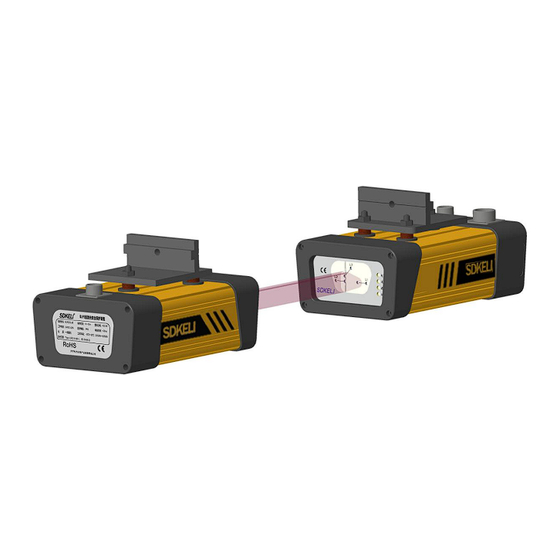
1.3.4 Cable specification Power&signal cable specification: Note:SR type controller and ST type controller power line common, No:CPSRX1X□□□□。 Receiver-Controller Transmission cable specification: Emitter-Receiver Transmission cable specification: 1.4. Sensor 1.4.1 Appearance Fig.1.3 Appearance of sensor - 8 -... -
Page 10: Dimensions
The front protection area is formed in the range of L1 receiving hole, and the middle protection area is formed in the range of L2 and L3 receiving holes. Fig.1.4 Panel of sensor Sensor Color Description indicators Emitter Power Orange Turns on when the power is on. -
Page 11: Controller
1.5. Controller 1.5.1 Appearance Fig.1.6 Appearance of SR/SP controller Name Description Power Yellow indicator light, when the power is turned on, the light is on. Fault Red indicator light, when the system detects a fault, the light is on. Green indicator light, when the system output relay contact is on, the light OSSD ON is on. - Page 12 Fig.1.7 Appearance of ST controller Number Name Description 10 yellow indicator lights indicate the current program number. There are 10 processes in total. When the controller status is in a certain process, the Process yellow indicator light of this process is on, and the other process lights are off.
-
Page 13: Dimensions
1.5.2 Dimensions Fig.1.8 Dimensions of SR/SP controller Fig.1.9 Dimensions of ST controller - 12 -... -
Page 14: Cables
1.6. Cables 1.6.1 Power cable Power cable is the 7-core butyl sheath shield cable with a 7-core hole-plug end connected to the controller and each core at the other end of the cable is crimped with binding terminal to connect to the bending machine. The number, color and function of the cores are shown as follows: Fig.1.10 Power cable 1.6.2 Signal cable... -
Page 15: Transmission Cable
1.6.3 Transmission cable Single-end cable The single-ended transmission line uses a 10-core butyl sheath shield cable, one end is a 12-core hole-plug, which is connected to the sensor, and the other end is crimped to the terminal with each core and connected to the bending machine. The serial number, color and function of each core are as shown in the figure below: Fig.1.13 Single-end cable ... - Page 16 Socket pin Signal CANH CANL OSSD1 (L1) OSSD2(L1) definition Wire color Green Yellow Black Blue Brown Socket pin Signal OSSD1 (L2) OSSD2(L2) OSSD1 (L3) OSSD2(L3) definition Yellow&Gre Wire color White Gray Cyan Purple Cable specifications list: Standard line Usage Name Specifications Number Connecting devices...
-
Page 17: Mounting Brackets
1.7. Mounting brackets Fig.1.16 Dimensions of linear bracket 1.8. Technical parameters Sensor technical parameters: Security category Safety type Type 4(IEC 61496) PL e(ISO 13849) Executive 2006/42/EC (Machinery Directive) 2014/30/EU (EMC Directive) standard IEC 61496-1 IEC 61496-2 ISO 13849-1 DCavg MTTF(Year) 95 MTTF (... - Page 18 Environmental characteristics Ambient Operation:-10℃~55℃(without frost and Storage:-40℃~70℃ temperature fog) Ambient Operation:35%RH~85%RH Storage: 35%RH~95%RH humidity Protection IP65 level Environmental Incandescent lamp:3000 Fluorescent lamp:3000 Sunlight: 10000 Lux illuminance Homologous light Interference light from the same design transmitter will not cause the BLPs to fail interference Anti-vibration The frequency is 10-55hz, the amplitude is 0.35 ±...
- Page 19 ST controller technical parameters: Project Parameter Ambient Operation: -10℃~55℃(without frost and Storage:-40℃~70℃ temperature fog) Ambient humidity Operation:35%RH~85%RH Storage:35%RH~95%RH Protection level IP54 Dimensions 195×180×82mm Supply voltage DC24V±20% Total power ≤15W consumption OSSD1/OSSD2 Two-way relay normally open contact (main control output) Output form ALARM PNP alarm output OSSD1/OSSD2...
-
Page 20: Section2 Function Introduction
Section2 Function introduction 2.1 Input/Output interface circuit 2.1.1 Interface circuit of sensor Fig.2.1 Interface circuit of sensor Signal and wiring introduction: Signal label Meaning of signal Wiring DC24V Anode of power supply Connect with anode of power supply DC0V Cathode of power supply Connect with cathode of power supply Connecting to the ground Control output interface of L1, PNP... -
Page 21: Interface Circuit Of Controller
2.1.2 Interface circuit of controller SR controller Fig.2.2 Interface circuit of SR Signal and wiring introduction: Signal label Meaning of signal Wiring Connect to the right power supply A1/A2/PE Power input according to the rated voltage Reference high- level signal output of Provide high-level voltage for external the controller relay contacts... - Page 22 SP controller Fig.2.2 Interface circuit of SP Signal and wiring introduction: Signal label Meaning of signal Wiring Connect to the right power supply according to A1/A2/PE Power input the rated voltage Reference high- level signal Provide high level voltage for external relay output of the controller contacts Connect to the NO contacts of the relay which...
-
Page 23: Function Declaration
ST controller Fig.2.3 Interface circuit of ST Signal label Meaning of signal Wiring Connect to the right power supply A1/A2/PE Power input according to the rated voltage Reference high- level signal output of Provide high level voltage for external the controller relay contacts Connect to the NO contacts of the relay... -
Page 24: Monitoring Function
2.2.2 Monitoring function Monitoring the state of sensor BLPS monitors the state of the detecting beams and outputs safety control signals according to the operating mode and the detecting results Such as: in the protection trip, if the effective detecting beam is shaded, the OSSD outputs are on the OFF-state. -
Page 25: Operating Mode
NOTE: This function is only offered by SP controller. 2.3 Operating mode 2.3.1 Sensor used alone The operating mode can be set by the assist of control system of the bender when sensor is used separately. 2.3.2 Sensor and SR controller used together SR controller provides three operating modes: normal mode, folding box mode and muting mode, using the mode switch (self-resetting) to change the operating mode. -
Page 26: Sensor And Sp Controller Used Together
Fig.2.5 Operational timing chart of folding box mode of SR Muting mode Under muting mode, all the protection areas (L1, L2, L3) are ineffective and SR controller can not provide protection. Fast down control output (13/14, 23/24) still keeps on ON-state even if there is an object in the detection area. - Page 27 being valid and the gearshift signal is invalid), slow down stroke and back stroke are not protected. Normal mode Under normal mode, all the protection areas (L1, L2, L3) are effective. Any beam is blocked in the protective stroke, fast down control output (13/14, 23/24) is cut off to prevent stroke start or stop it to avoid serious injury.
- Page 28 When the central protection area of sensor keeps on light-shaded state, trigger the down going signal again, the fast down control output and the slow down control output turn on at the same time and the bender will finish the working stroke at the set slow down speed. The folding box mode should be selected when the workpiece only blocks L1 protection areas before the bender change the speed of the working stroke, such as box-shaped parts.
-
Page 29: Sensor And St Controller Used Together
WARNING The muting mode may be selected when the bender processes complex shape workpiece. Other protection measures should be taken to protect the operator under this mode. 2.3.4 Sensor and ST controller used together ST type controller is a kind of bending machine safety protection device controller for multi-process bending of complex parts Compared with SR/SP type controller, the operating comfort of the device system is unchanged on the basis of the safety protection performance, which reliably protects the personal safety of the bending machine operator and proves the... - Page 30 St type normal function timing diagram: The front protective area laser (L1) of the normal mode sensor is shielded, and the middle protective area laser (L2, L3) plays a protective role. Fig.2.11 ST-type controller normal function timing diagram ST type shielding function timing diagram: Rejection mode: All lasers (L1, L2, L3) are shielded.
-
Page 31: Section3 Installation And Wiring
Section3 Installation and wiring Before installation, please read carefully the notes and warning information of this manual in order to avoid the personal injury caused by wrong installation. CAUTION BLPS can only be applied to the bender that is produced in compliance with the ... -
Page 32: Muting Point Setting
light source and the sensors to ensure the normal use of BLPS. Fig.3.2 External light interference 3.1.2 Muting point setting Muting point should be set before the use of BLPS to avoid the mistake that BLPS identifies the workpiece as an obstacle. Muting point: the point that BLPS will not output control signal, which is generally the same point with the gearshift point ( That is, when the upper die of the bending machine goes down, it is changed from fast to slow) of the bender. -
Page 33: Installation Of Sensor
Fig.3.4 Muting point position S >(t1+t2)×V+5 mm t1: the response time is less than 8ms,when calculating with t1=8ms; t2: the stopping response time of the bender; V: the fast downward clamping speed of the bender. The safety distance S is obtained in the following several ways. 1)Calculated by the formula(S >(t1+t2)×V+5 mm)... - Page 34 Wrong mounting diagram The height of the emitter is not the same as the receiver The horizontal mounting diagram of the detecting sensor of BLPS. Right mounting diagram The emitter and receiver are aligned right, the detecting beam parallels the upper die tip Wrong mounting diagram The emitter and receiver are not aligned right, the detecting beam does not parallel the upper die tip WARNING...
-
Page 35: Mounting Brackets
3.2.2 Mounting brackets Fig.3.5 Guide bracket Horizontal adjustment structure Fig.3.6 Horizontal adjustment structure Left position, right position and around the Z axis adjustment structure Fig.3.7 Left and right position adjustment structure - 34 -... -
Page 36: Installation Steps
Vertical adjustment structure Fig.3.8 Vertical adjustment structure Mounting hole dimensions Fig.3.9 Mounting hole dimensions 3.2.3 Installation steps 1 ) Select proper position on both sides of the bender slider, machine tool, drill and tap according to dimensions shown in Fig.3.10. Fix the horizontal bracket ① onto the slider by M8×25 inner hexagon screws. -
Page 37: Light Debugging
Fig.3.10 Installation diagram 3.2.4 Light debugging When BLPS is installed on site, the positional relationship between the laser spot and the die tip of the bending machine is very important. The correct position setting can effectively protect the personal safety of the operator, and the wrong position setting may make the laser safety protection device lose its protective effect. -
Page 38: Installation Of Controller
Fig 3.12 Schematic diagram of beam alignment Adjust the transmitter so that the spot is within the spot-shaped contour line on the aiming aid (transmitter side). Adjust the pitch and left and right angles of the transmitter so that the light spot passes through the L2 hole on the transmitter side 000, and at the same time passes through the L2 hole on the receiver side aiming aid. -
Page 39: Installation Of St Controller
Fig.3.15 Mounting dimensions of SR/SP controller 3.3.2 Installation of ST controller The ST controller is installed on the front of the upper die slider of the bending machine, where it is convenient for workers to operate, using two M6 × 12 screws to fix. Fig.3.16 Mounting dimensions of ST controller 3.4 Installation of optional accessories If the bender can not provide muting point signal, it is can be provided by optional accessories... -
Page 40: Limit Switch
Stop dog should be mounted on the rear area of both sides of the slider and mounting plate should be mounted on the both sides of the bender. Set the muting point by adjusting the relative position of limit switch (or approach switch), the stop dog and the mounting plate. For the related content, seL3.1.2. -
Page 41: Power Supply
3.5.2 Power supply WARNING The setting of the power BLPS must comply with the following requirements, otherwise, it may result in damage. To ensure the normally working of the laser safety protection device, the power supply must comply with the following requirements: ... - Page 42 Fig.3.21 Wiring diagram of sensor Sensor and controller used together Wiring procedures: 1) The transmission line connects the emitter to the receiver, and the receiver to the controller. 2)Signal cable is connected to the control system of the bender. 3)Connect to the power supply.
- Page 43 The wring diagram of SP controller is as followed: KA1—relay controlling slow down stroke KA2—relay controlling fast down stroke KA3—relay controlling return stroke KA4—foot switch of the bender Fig.3.23 Wiring diagram of SP The wring diagram of ST controller is as followed: KA1--relay controlling slow down stroke Fig.3.23 Wiring diagram of ST WARNING...
-
Page 44: Section4 Check And Debugging
Section4 Check and debugging WARNING Make sure to test the operation of BLPS after installation to verify that BLPS operates as intended. Make sure to stop the machine until the test is complete. Unintended function settings may cause a person to go undetected, resulting in serious injury. After installation, the equipment manager must check according to the following terms, and record the results. -
Page 45: Operation Check While The Bender Operates
B. Remove the test piece from the detecting area, the L1, L2 and L3 indicators in the receiver should be turned off. 4.4 Operation check while the bender operates □ The hazardous parts should change the state according to the pre-set program (speed change or stop) immediately when the test piece blocks any beam of L1,L2 or L3. -
Page 46: Section5 Maintenance
Section5 Maintenance WARNING Perform daily and 6-month inspection for BLPS. Otherwise, the system may fail to work properly, resulting in serious injury. Do not try to disassemble, repair, or modify this product. Doing so may cause the safety functions to stop working properly. - Page 47 □ The changing of machine setting should not affect the safety of the control system. □ The beam position and safe distance complies with the setup requirements. - 46 -...
-
Page 48: Section6 Troubleshooting
Section6 Troubleshooting WARNING Do not disassemble, repair, or modify this product. Otherwise, BLPS may not realize its safety function and will lead to serious injuries. 6.1 Fault analysis If an error is detected, BLPS enters lockout state, the output of OSSD keeps OFF-state. The fault indicators on the emitter and receiver turn on. -
Page 49: Braking System Fault Of The Bender
6.2 Braking system fault of the bender Phenomenon Cause Solution The connection between the control output of BLPS and Check the control output circuits The indicators conversion of the electrical system of the BLPS is normal, but the bender bender is open or wrong. does not operate The electrical trouble of the Check the circuits of the bender... - Page 50 Manufacture:Jining Keli Photoelectronic Industrial CO.,Ltd TEL:+86-0537-2168110 FAX:+86-537 2331667 Http://www.sdkeli.com Service Hotline:400 666 0416 ADD: No. 46 Haichuan Road, High-tech Zone, Jining City, Shandong Province...
Need help?
Do you have a question about the BLPS-D3L and is the answer not in the manual?
Questions and answers