
Related Manuals for Centa CENTAX-L


Summary of Contents for Centa CENTAX-L
- Page 1 CENTAX-L Assembly and operating instructions 016L-00050…00090-FS10 M016-00003-EN Rev. 3...
-
Page 2: Table Of Contents
Mounting the link flange assembly and the adapter (8) ....30 Mounting the links ................32 After completed mounting ..............36 Operation....................37 Operating faults, root causes and remedy ..........37 Admissible overall misalignment of the coupling ........37 CENTA Antriebe Kirschey GmbH 2 / 46... - Page 3 Wearing and spare parts............... 44 Annex ....................45 11.1 CENTA data sheet D013-013 (lubricated screw connections) ....45 11.2 CENTA data sheet D016-900 Declaration of incorporation according to the EC Machinery Directive 2006/42/EC, Appendix II B ......46 CENTA Antriebe Kirschey GmbH...
- Page 4 Table 2-1 Shape and size of ventilation holes ..........8 Table 5-1 Permissible radial alignment tolerance .......... 15 Table 5-2 Permissible angular alignment tolerance ........17 Table 6-1 Guide to links ................33 Table 7-1 Troubleshooting table ..............37 CENTA Antriebe Kirschey GmbH 4 / 46...
-
Page 5: General Remarks
In the interests of further development, CENTA reserves the right to make technical changes. IMPORTANT CENTA is unable to accept liability for damage and operating faults caused by failure to observe the operating instructions. These operating instructions are protected under copyright to CENTA Antriebe Kirschey GmbH. -
Page 6: Safety
Denotes a potentially dangerous situation. CAUTION If not prevented, minor injuries and/damage to property may result. Denotes application tips and particularly useful information. This is not IMPORTANT a signal word denoting a dangerous or damaging situation. CENTA Antriebe Kirschey GmbH 6 / 46... -
Page 7: Pictograms
Injury and material damage can occur as a result of: Application not in compliance with the intended use The couplings are intended exclusively for use in accordance with the relevant design. They may only be used under the specified conditions. CENTA Antriebe Kirschey GmbH 7 / 46... - Page 8 Shield the coupling in accordance with the applicable accident prevention regulations with an enclosure. Exception: The coupling is encased by the driving and driven units. The scope of delivery provided by CENTA does not include a protective enclosure. This enclosure must fulfil the following criteria: ...
-
Page 9: Application Not In Compliance With The Intended Use
Only use the coupling for the specified application. CENTA bears no liability for damage resulting from application not in compliance with the intended use of the equipment. Should there be a change of plant parameters, the coupling design must be reviewed by CENTA (address see chapter 1). -
Page 10: Delivery, Transport, Storage And Disposal
IMPORTANT Rubber parts are marked where possible with their production date. From this date, they may only be stored for a maximum of 5 years. CENTA Antriebe Kirschey GmbH 10 / 46... -
Page 11: Storage Location
Ensure safe, environmentally responsible disposal of operating supplies and exchange parts. For this, locally provided recycling facilities and regulations must be utilized. For disposal, the coupling parts must be separated where possible and sorted according to material type. CENTA Antriebe Kirschey GmbH 11 / 46... -
Page 12: Technical Description
Technical description Characteristics The CENTAX-SEC series L coupling have the following excellent characteristics, due to the combination of a torsionally flexible CENTAX element and the CENTA link coupling with axial angular movement: Compensation of torsional vibrations and impacts without wear. -
Page 13: Alignment Of The Units Being Connected
Determine the axial misalignment (see Fig. 5-1). Take installation length L from the installation drawing. Align the units (installation dimension = L±∆K A max Permissible axial alignment tolerance: ∆K =0.5 mm A max Fig. 5-1 Axial misalignment CENTA Antriebe Kirschey GmbH 13 / 46... -
Page 14: Radial Alignment
Turn the hub with dial gauge and flywheel slowly by 360°. Align the units (calculated deviation ≤∆K R max The permissible radial alignment tolerance ∆K can be found in the following R max table. Fig. 5-2 Radial misalignment CENTA Antriebe Kirschey GmbH 14 / 46... - Page 15 50 / 60 ±0.82 ±0.25 50 / 60 ±0.9 ±0.3 50 / 60 ±1.05 ±0.33 50 / 60 ±1.05 ±0.37 82 - 90 50 / 60 ±1.2 ±0.37 Table 5-1 Permissible radial alignment tolerance CENTA Antriebe Kirschey GmbH 15 / 46...
-
Page 16: Angular Alignment
The permissible tolerance S should be taken from the table below. W max Align the units (calculated deviation ≤∆K W max Permissible angular alignment tolerance: ∆K =0.2° W max Fig. 5-3 Angular misalignment CENTA Antriebe Kirschey GmbH 16 / 46... - Page 17 Assembly and operating instructions M016-00003-EN Rev. 3 CENTAX-L 016L-00050…00090-FS10 SAE J620 W max DIN 6288 [mm] [mm] 1060 1120 Table 5-2 Permissible angular alignment tolerance CENTA Antriebe Kirschey GmbH 17 / 46...
-
Page 18: Mounting
Always cushion parts when supporting them from below. CAUTION Material damage can occur as a result of: Soiled joint surfaces The surfaces that are to be joined must be free of dirt, preservatives and lubricants. CENTA Antriebe Kirschey GmbH 18 / 46... - Page 19 This type of screw locking medium may not be in contact with rubber parts. IMPORTANT Screw preparation and tightening torque levels in accordance with CENTA data sheet D013-013 (see chapter 11.1). Use suitable lifting devices for assembly. The following assembly stages are described for coupling 016L-00064-FS10.
-
Page 20: Mounting Overview
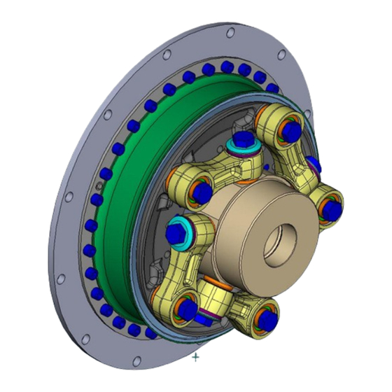
Assembly and operating instructions M016-00003-EN Rev. 3 CENTAX-L 016L-00050…00090-FS10 Mounting overview The following figures are showing examples of possible design. Fig. 6-1 Example: 016L-00064-FS10 Fig. 6-2 Example: 016L-00064-FS10 CENTA Antriebe Kirschey GmbH 20 / 46... - Page 21 Positioning the link flange assembly (1), see chapter 6.5 . Mounting the link flange assembly (1), see chapter 6.6 . Mounting the links, see chapter 6.7 . After completed mounting, see chapter 6.8 . CENTA Antriebe Kirschey GmbH 21 / 46...
-
Page 22: Mounting The Hub
6.3.2 . 6.3.1 Mounting the hub with cylindrical bore and keyway Fig. 6-3 Mounting the hub with cylindrical bore and keyway Item Info Designation Remark Shaft Customer part Face of shaft Face of hub CENTA Antriebe Kirschey GmbH 22 / 46... - Page 23 Face of shaft must not protrude to face of hub. Otherwise radial replacement of other coupling parts is not guaranteed. CAUTION Material damage can occur as a result of: Hot hubs/flange hubs Before further mounting of hubs/flange hubs, allow them to cool to ambient temperature. CENTA Antriebe Kirschey GmbH 23 / 46...
-
Page 24: Mounting The Hub With Conical Oil Interference Fit
G¼ or G¾ see installation drawing Lightly oil the cone of the shaft (A). Push the hub (3) onto the shaft (A). Remove the screw plug (19) from the hub (3). CENTA Antriebe Kirschey GmbH 24 / 46... - Page 25 The increase of the expanding pressure may not exceed 35 bar/minute. WARNING Material damage can occur as a result of: Insufficient expanding pressure in the hub If the expanding pressure is too low, the necessary pushing pressure is too high. CENTA Antriebe Kirschey GmbH 25 / 46...
-
Page 26: Aligning The Units
Face of shaft must not protrude to face of hub. Otherwise radial replacement of other coupling parts is not guaranteed. Aligning the units Align the units to be connected (see chapter 5). CENTA Antriebe Kirschey GmbH 26 / 46... -
Page 27: Positioning The Link Flange Assembly (1)
Position the link flange assembly (1) between the hub (3) and flywheel (B). Slide the link flange assembly (1) over the hub (3) and place down on the hub. The centrings for the links (d) must point towards the hub (3). CENTA Antriebe Kirschey GmbH 27 / 46... -
Page 28: Mounting The Link Flange Assembly (1)
Fig. 6-6 Mounting the link flange assembly with/without sheet (5) Item Info Designation Remark Link flange assembly Pre-mounted by CENTA Sheet See installation drawing Washer If ordered Screw If ordered Flywheel Customer part CENTA Antriebe Kirschey GmbH 28 / 46... - Page 29 Screw the link flange assembly (1) to the flywheel (B) using the screws (30) and the washers (31). IMPORTANT Tightening torques for elements to connect couplings with customer parts could deviate from CENTA data sheet D013-013. Consider specifications on installation drawing. CENTA Antriebe Kirschey GmbH 29 / 46...
-
Page 30: Mounting The Link Flange Assembly And The Adapter (8)
Screw the adapter (8) to the flywheel (B) using the screws (30) and the washers (31). IMPORTANT Tightening torques for elements to connect couplings with customer parts could deviate from CENTA data sheet D013-013. Consider specifications on installation drawing. CENTA Antriebe Kirschey GmbH 30 / 46... - Page 31 Adapter Screw ISO4762-10.9 Washer (not shown) See installation drawing Drilling for bolt in adapter Drilling for bolt in link flange assembly IMPORTANT Ensure during installation that the bolts are in the right position. CENTA Antriebe Kirschey GmbH 31 / 46...
-
Page 32: Mounting The Links
Instructions on how to mount one link are provided following. Item numbers and the part illustrations may differ slightly from the delivery state. The following table gives an overview of the number of size of the links used. CENTA Antriebe Kirschey GmbH 32 / 46... - Page 33 Assembly and operating instructions M016-00003-EN Rev. 3 CENTAX-L 016L-00050…00090-FS10 CENTALINK CENTAX Link Size Size Size Quantity 48/50 50/52/55/56 60/65/67 64/65/67 69/70/71 176/276 177/277 80/81 80/81 179/181/279/281 82/84/85 82/84/85 183/184/283/284 Table 6-1 Guide to links CENTA Antriebe Kirschey GmbH 33 / 46...
- Page 34 Assembly and operating instructions M016-00003-EN Rev. 3 CENTAX-L 016L-00050…00090-FS10 Fig. 6-9 Mounting the links ("ccw" counterclockwise rotation) Fig. 6-10 Mounting the links ("cw" clockwise rotation) CENTA Antriebe Kirschey GmbH 34 / 46...
- Page 35 Repeat the mounting section above until all links are mounted (for quantity of the links, please see the table guide to links). Fasten the screws (6 and 7) of the link unit (1) by required tightening torque "crosswise". CENTA Antriebe Kirschey GmbH 35 / 46...
-
Page 36: After Completed Mounting
Injury and material damage can occur as a result of: Loose screw connections Before commissioning, the tightening torque levels of all screws must be checked and corrected if necessary. Before commencing long-term operation, the plant must successfully complete a test run. CENTA Antriebe Kirschey GmbH 36 / 46... -
Page 37: Operation
In case of uncertainty or if you have questions, please contact our head office (address see chapter 1). Admissible overall misalignment of the coupling The overall misalignment values can be found in the catalogue. CENTA Antriebe Kirschey GmbH 37 / 46... -
Page 38: Care And Maintenance
When replacing the rubber elements IMPORTANT Links are packaged in sets. All links of a link set are the same weight. Only mount or replace links in complete sets. CENTA Antriebe Kirschey GmbH 38 / 46... -
Page 39: Visual Inspection Of The Rubber Elements / Rubber Segments
Exchange the rubber elements / rubber segments in the event that: The wear specifications given in W000-00002 are exceeded Assess the rubber elements / rubber segments as described in CENTA guidelines W000-00002. 8.1.5 Inspection of the screw connections ... -
Page 40: Dismantling
Contact with sharp-edged objects Protect coupling components for transportation. Only hoist coupling components with nylon belts or ropes. Always cushion parts when supporting them from below. IMPORTANT Use suitable lifting devices for dismantling. CENTA Antriebe Kirschey GmbH 40 / 46... -
Page 41: Dismantling The Links
See Fig. 6-5: Remove the link flange assembly (1) out of the installation space. Pull the circlips (7; 2x180°) from the bolts (6) and remove as well as the the bolts. CENTA Antriebe Kirschey GmbH 41 / 46... -
Page 42: Dismantling The Hub (If Necessary)
Injury and material damage can occur as a result of: Hydraulic fluid spraying out Use protective goggles. WARNING Injuries and material damages can occur by: Suddenly loosening hubs Secure the hub with a hydraulic tool against sudden axial loosening. CENTA Antriebe Kirschey GmbH 42 / 46... -
Page 43: Reassembling The Coupling
Turn the hub (3), drain oil out of the thread G¼ or G¾ (c) and dispose correctly. Screw the screw plug (19) into the hub (6). Remove the hub (3) from the shaft (A). Reassembling the coupling Reassemble the coupling as described in chapter 6. CENTA Antriebe Kirschey GmbH 43 / 46... -
Page 44: Wearing And Spare Parts
A stock of the most important wearing and spare parts is the most important condition to ensure that the coupling is functional and ready for operation at all times. We only provide a warranty for CENTA original parts. Wearing parts of this coupling: ... -
Page 45: Annex
CENTAX-L 016L-00050…00090-FS10 Annex 11.1 CENTA data sheet D013-013 (lubricated screw connections) Validity: For all non-dynamically stressed screw connections with lubricated shank bolts in accordance with ISO 4014, ISO 4017 and ISO 4762 (DIN 912) with metric standard thread in accordance with DIN ISO 262, unless other specifications are given on CENTA documents. -
Page 46: Centa Data Sheet D016-900 Declaration Of Incorporation According To The Ec Machinery Directive 2006/42/Ec
+49-2129-2790 Bergische Strasse 7 centa@centa.de 42781 Haan / GERMANY www.centa.info We herewith declare that the incomplete machine Product: Highly elastic coupling CENTAX-L Model / series code: CX-L / 016L Installation size: 50…90 Design: Serial number: according to shipping documents, if applicable...
Need help?
Do you have a question about the CENTAX-L and is the answer not in the manual?
Questions and answers