Table of Contents
Advertisement
Advertisement
Table of Contents

Summary of Contents for CHOWEL TB40-P02A
- Page 2 ----- Important ----- Read first this manual before operate this device. In some case, failure to follow this manual can lead to control or machine damage. In other cases failure to follow instructions can lead to injury, or death of personnel. This manual explains some instructions depends on the level of danger as follows.
- Page 3 READ FIRST To use this device in safety, he/she should follow industry standards and safety senses whenever working on, or near the weld machine. In some case, failure to follow the warning instructions can lead to damage. In other cases failure to follow these instructions can lead to injury, or death of personnel.
- Page 4 Preface This teaching box is designed to obtain CE marking and is based on following standards. [EN50011-2], [EN50082-2] [EN60204-1], [EN61000-4-2], [EN61000-4-4], [EN61000-4-5], [EN61000-4-8], [ENV50140], [ENV50141] etc. TB40 ! WARNING a. Understand fully this manual before you attend to work. b. Keep this manual in decided place in order to read this manual easily and regularly. c.
-
Page 5: Table Of Contents
Contents 1. Outline 2. Notes to Handling 3. Description of Each Part 4. Normal Display 5. Error / Fault Display 6. Function Select Modes 6-1. Function Select 6-2. Teaching Mode Change 6-3. Data Name / Data Range Change 6-4. Backlight ON/OFF Change 6-5. -
Page 6: Outline
1. Outline The teaching box is option for welding controller. The teaching box has features as follows: - Display / input of program data in a spread sheet format. - Function select in menu. Data copy function, various counter data clear functions, etc. - Error alarm with buzzer sound. -
Page 7: Description Of Each Part
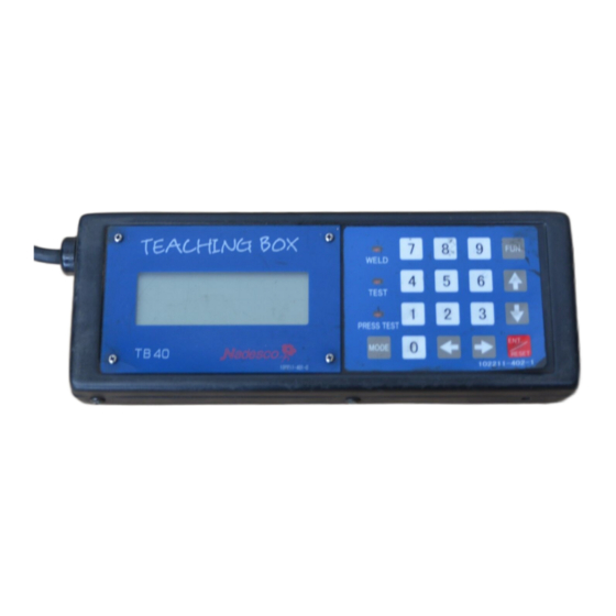
3. Description of Each Part (1) Attaching / detaching connectors (2) LCD window If the teaching box is not operated for about 3 minutes or there is no error caused for about 3 minutes, the backlight will be automatically turned OFF. If some key is hit then, the backlight will be turned ON again. - Page 8 (3) Keyboard Figure keys : Input data keys Arrow keys : Select address keys Instruction of each mode operation WELD OPERATION : Sequence is active and weld. TEST : Sequence active and not weld. (At installation) PRESS TEST : There is no sequence operation but there is only turning ON/OFF of the VALVE OUTPUT in accordance with ON/OFF of the PILOT INPUT.
-
Page 9: Normal Display
4. Normal Display After the power supply for the welding controller is turned ON, or after the teaching box is connected, the LCD display appears as shown in Fig. 4-1. Fig. 4-1 (1) SCHE 1 : This is a X address. X addresses can be shifted by the ←... - Page 10 mode. (Refer to 6-2. Teaching mode change) (6) : This indicates PILOT (START). When "*" is shown, it means that the PILOT is ON. (7) : This indicates the timer slave station number (TIMER No.). This display is the hexadecimal 0 through F as a decimal 0 through 15.
-
Page 11: Error / Fault Display
5. Error / Fault Display (1) Communication Error This error is displayed as shown in Fig. 5-1. Check the communication cable. Fig. 5-1 (2) Other error / fault Other error / fault is displayed as shown in Fig. 5-2 with the error code and the start schedule No. -
Page 12: Function Select Modes
6. Function Select Modes 6-1. Function Select Press the FUN. key, and the LCD display will turn to be as shown in Fig. 6-1-1. Fig. 6-1-1 In this case, each keys has its own function as follows: ↓ : Moves the cursor ↑... -
Page 13: Teaching Mode Change
Other keys than the above : Returns to the normal display. 6-2. Teaching Mode Change As described in Fig. 4-1 (5), the teaching box is provided with the teaching mode which can be divided further into the following two modes: PROG : Program enable (data input enable) mode. -
Page 14: Backlight On/Off Change
6-4. Backlight ON/OFF Change To change the backlight ON/OFF, use the following key strokes: 1. FUN. 2. 1 : Execute the ON/OFF change. 1. FUN. 2. ↑ ↓ : Bring the cursor to "1=BACK LIGHT ON/OFF". 3. ENT./RESET : Execute the ON/OFF change. The LCD display resumes to the normal display. - Page 15 data type and press the key of the number. If key is pressed, for example, the LCD display will turn to be as shown in Fig. 6-5-3. Fig. 6-5-3 Press the ENT./RESET key, and the bottom line in the LCD display will turn to be as shown in Fig.
- Page 16 Fig. 6-5-7 If some key is hit then, the normal display as shown in Fig. 6-1-1 will be resumed. - Caution of copy function (1) When copying from the T/B to the welding controller, the message "WRITE INHIBITED" sometimes be showed. This indicate the data of the T/B is outside the range of the welding controller data.
- Page 17 Fig. 6-5-10 If some key is hit then , the normal display as shown in Fig. 6-1-1 will be resumed. - When there is no discrepancy between the data The display in the bottom line as shown in Fig. 6-5-9 will turn to be as shown in Fig. 6-5-11. Fig.
-
Page 18: Reset Various Functions
6-6. Reset Various Functions To change the mode to the Reset Various Functions modes, use the following key strokes. 1. FUN. 2. 3 : Execute the mode change. 1. FUN. 2. ↑ ↓ : Bring the cursor to "3=RESET VARIOUS FUNC." 3. -
Page 19: Data Initialize
If the Stepper No. not existing is inputted, LCD display will turn to be as shown in Fig. 6-6-4. Press any key. The display as shown in Fig. 6-1-1 will be resumed. Fig. 6-6-4 If 1 and 3 are pressed following the display of Fig. 6-6-2, it becomes as it is shown in Fig. -
Page 20: Schedule Duplicate
! CAUTION About initialize data, refer to the instruction manual of welding controller. To initialize the weld data, use the following key strokes. 1. FUN. 2. ↑ ↓ : Bring the cursor to "4=DATA INITIALIZE". 3. ENT./RESET : The LCD display will turn to be as shown in Fig. 6-7-1. Fig. - Page 21 To execute the schedule duplicate, continue the procedure as follows: 1. Key in the schedule No. of the duplicate source. If the number shown in (1) is the same as this schedule No., there is no need to take this step. ENT./RESET : Bring the cursor to (2).
- Page 22 If the schedule No. previous to the schedule duplicate mode is 2, the LCD display will turn to be as shown in Fig. 6-8-4. Fig. 6-8-4 - To continue the schedule duplicate 1. 3 : Key in the schedule No. of the duplicate source. 2.
- Page 23 5 , ENT./RESET : Specify the range of the schedule No. of the duplicate destination. The LCD display will turn to be as shown in Fig. 6-8-9. ( 2 and 15 may be exchanged in order.) Fig. 6-8-9 5. ENT./RESET : Execute the duplicating, and the normal display will be resumed.
-
Page 24: Timer Slave Station No. Confirm / Change Mode
6-9. Timer Slave Station No. Confirm / Change mode ! CAUTION This function is applicable only to the welding controller provided with communication function. To change the mode to the timer slave station No. confirm / change mode, use the following key strokes. - Page 25 Fig.6-9-3 Input the timer slave station No. and press ENT./RESET key. The normal display will be resumed. If the timer slave station No. that is not connected is tried to be set, the display will turn to be as shown in Fig. 6-9-4 and the previous timer slave station No. will be resumed. Fig.
- Page 26 Fig. 6-9-7 - Change the timer slave station No.. 1. ENT./RESET : Turn to the change mode. Fig. 6-9-8 2. 2 , ENT./RESET : Input the desired timer slave station No. Fig. 6-9-9 Then, the normal display will be resumed. (2) Confirm / change the timer slave station No.( welding controller ).
- Page 27 Fig. 6-9-12 ! CAUTION This function is effective in welding controller that has communication function. Note of setting timer slave station No. (1) If 0 is set as the timer slave station No. of the welding controller linked, a teaching box will communicate only with the welding controller that the timer slave station No.
- Page 28 Fig. 6-9-14 (3) Before welding controller linked, set the timer slave station No. every set.
-
Page 29: Input / Output Monitor
6-10. Input / Output Monitor ! CAUTION This function is applicable only to the welding controller that is able to monitor the input and output signal. To monitor the state of input and output, use the following key strokes: 1. FUN. 2. -
Page 30: Device Net Setting
! CAUTION Assignment (signal name) of each bits in monitor data is different depending on the specific model. Refer to the instruction manual of welding controller. And this function is applicable only to the welding controller that is able to monitor the input and output signal. -
Page 31: Cc Link Setting
and press the ENT./RESET key. The LCD display will turn to be as shown in Fig. 6-11-3. Fig. 6-11-3 The data rate set up first is displayed. When changing, input the number to change, and then press the ENT./RESET key. It is changed when the ENT./RESET key is pressed. A setup is performed in the number from 0 to 2. -
Page 32: Ether Net Setting
Following the display of Fig. 6-12-1, Press the 1 key or bring the cursor to the line of 1 and press the ENT./RESET key. The LCD display will turn to be as shown in Fig. 6-12-2. Fig. 6-12-2 The timer slave station No. set up first is displayed. When changing, input the address (number) to change, and then press the ENT./RESET key. - Page 33 The LCD display will turn to be as shown in Fig. 6-13-1. Fig. 6-13-1 (1) Confirm / change the IP address Following the display of Fig. 6-13-1, Press the 1 key or bring the cursor to the line of 1 and press the ENT./RESET key.
-
Page 34: Profibus Setting
Fig. 6-13-4 The gate way address set up first is displayed. When changing, bring the cursor to the target byte data, and input the number to change, and then press the ENT./RESET key. It is changed when the ENT./RESET key is pressed. Each byte data of the setting range is 0 to 255. -
Page 35: Date / Time Confirm / Change Mode
Following the display of Fig. 6-14-1, Press the 2 key or bring the cursor to the line of 2 and press the ENT./RESET key. The LCD display will turn to be as shown in Fig. 6-14-3. Fig. 6-14-3 The data rate set up first is displayed. The transfer rate of profibus is automatic. Change of the transmission rate by the side of a welding controller cannot be performed. -
Page 36: Write Collectively
6-16. Write Collectively To change the mode to the Write collectively mode, use the following key strokes. 1. FUN. 2. ↑ ↓ : Bring the cursor to "x=WRITE COLLECTIVELY" 3. ENT./RESET : Execute the mode change. The LCD display will turn to be as shown in Fig. 6-16-1. Fig. - Page 37 Ex.) When writing data 82.6 into the Y address 20 of the schedule No.3-14. - To change the mode to the Write collectively mode 1. FUN. 2. ↑ ↓ : Bring the cursor to "x=WRITE COLLECTIVELY" 3. ENT./RESET : Execute the mode change. - To execute the Write collectively 1.
-
Page 38: Error History
Fig. 6-16-8 6-17. Error history ! CAUTION This function is applicable only to the welding controller that is able to monitor the error history. To monitor the state of error history, use the following key strokes: 1. FUN. 2. ↑ ↓... - Page 39 Fig. 6-17-3 Bring the cursor to "2=ERASE" and press the ENT./RESET key. After the execution of erasing error history, the LCD display will turn to be as shown in Fig. 6-17-4, and the function select display will be resumed. Fig. 6-17-4...
-
Page 40: Other Functions
7. Other Functions In case of writing transfer of data to different timer in the same model or coping data to similar model after coping data from a certain timer with T/B, there may be the following display. Fig. 7-1 This message will be displayed in case of data item being different between original data item and data item copied with software change etc. - Page 41 Fig. 7-5...
Need help?
Do you have a question about the TB40-P02A and is the answer not in the manual?
Questions and answers