Advertisement
GENERAL DESCRIPTION
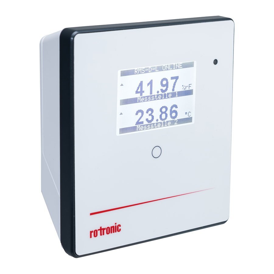
The Rotronic RMS display is a freely configurable display. As a remote display, it can be placed optimally where it suits the viewer best. The display is able to show the measured values, states and alarms of RMS products. These short instructions describe the main functions of the device.
COMMISSIONING
The device must be supplied with 24 V (terminals: V+ / V-) or PoE to be able to transmit data. The display can be mounted easily with the wall bracket. The device is connected to the RMS software by pairing.
WICHTIG: PORT80, DHCP
To integrate a LAN device, port 80 (per standard, please confirm with your IT department) must be enabled in your network and a DHCP server (for fixed IP addresses, please see your IT department) must assign the IP address to the device.
DELIVERY PACKAGE
- Display
- Wall bracket
- Short instruction manual
INTEGRATION OF THE DISPLAY (PAIRING) IN 6 STEPS
- If you do not want to connect the device to the Rotronic Cloud, the server must be configured in the device.
- Connect the device to the local network and start the RMS configuration software.
- Search for the device under Device > Search > Network Device. The software finds all RMS devices in the local network.
- Enter the host (server address) and the URL of the software-services under Settings.
- Finish configuration with Write.
- Log into the RMS software / cloud. Select Tools > Setup > Devices > New > LAN device.
 - Step 1")
- Enter the serial number of the device.
 - Step 2")
- Wait until the device flashes orange. Briefly press the button on the device as shown in the picture of the RMS software. The LED flashes green when connection is successful.
 - Step 3")
- Configure the device.
 - Step 4")
- Finish configuration.
 - Step 5")
 - Step 1")
 - Step 2")
 - Step 3")
 - Step 4")
 - Step 5")
LED INDICATORS
| Button | Mode | Status |
| Pairing | ||
| 1 s | Confirms pairing | n x orange, the indicator flashes while the pairing request is running |
| Show device status | ||
| Automatic (every 5 seconds) | Shows the current status | 1 x green, connection to server okay 2 x red, no server connection |
ACCESSORIES
AC1321: Mounting kit with Allen key and mounting cone
TECHNICAL DATA
| General specifications | |
| Device type | RMS Display |
| Display of measuring points | Up to 4 measuring points |
| Range of application | -20...70°C / 0...100 %RH |
| Storage conditions | -20...30°C / 0...95 %RH |
| Power supply | 24 VDC ±10% / <100 mA / PoE: 802.3 / af-2003, Class 1 |
| AC adapter requirements | 24 VDC ±10% / >4 W / power-limited |
| Measurement interval | 10 s |
| Interface | Ethernet |
| Protocols | HTTP |
| Conformity with standards | |
| FDA / GAMP directives | FDA CFR21 Part 11 / GAMP 5 |
| Housing / Mechanical parts | |
| Housing material | PC, ABS |
| Fire protection class | UL94-V2 |
| Dimensions | 105 x 113 x 38 mm |
| Display diagonal | 2.26 inch |
| IP protection class | IP65 |
| Weight | 206 g |
DIMENSIONS

Documents / ResourcesDownload manual
Here you can download full pdf version of manual, it may contain additional safety instructions, warranty information, FCC rules, etc.
Advertisement

Need help?
Do you have a question about the RMS-D-L and is the answer not in the manual?
Questions and answers