Table of Contents
Advertisement
Quick Links
Advertisement
Table of Contents

Related Manuals for World Uniqueen EN-508

Summary of Contents for World Uniqueen EN-508
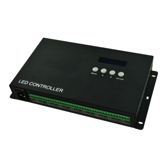
- Page 1 EN-508 MANUAL Version: 3. Model: EN-508-F10 2021-4...
-
Page 2: Table Of Contents
CONTENTS 1. FUNCTION OVERVIEW................................1 2. TECHNICAL PARAMETERS..............................1 3. CONNECTION MODE................................2 3.1. PORT INTRODUCTION..............................2 3.2. CONNECTION DIAGRAM OF CONTROLLER........................2 3.3. OPTICAL FIBER COMMUNICATION..........................3 3.4. CONNECT WITH LIGHTING FIXTURE..........................3 3.5. TRANSMISSION DISTANCE............................4 4. BASIC OPERATION................................4 4.1. MENU INTRODUCTIION............................... 4 4.2. -
Page 3: Function Overview
1. FUNCTION OVERVIEW 1. Support access and control by Madrix software or LED Player software. 2. Unique data processing method for the display with complex shape, it’s easy to make a solution. 3. It supports 1,000,000 channels or cascade connection of 400 pieces controllers. 4. -
Page 4: Connection Mode
2.Please do connect the earth safely in order to reduce risks of fire and damage which cause by short circuit. 3.Please ensure AC100-240V power supply is used, and same polarity is connected between transformer and controller in order to guarantee the proper supply voltage. 4.No waterproof function in the control system, please pay attention on rainproof and waterproof during installing. -
Page 5: Optical Fiber Communication
3.3. OPTICAL FIBER COMMUNICATION Must use single mode transceivers. User can use single fiber or double fiber (alternative) according to on-site condition. The double fiber transceiver must be connected with two optical fibers. It cannot use in EN controller when ID is 00 and the connecting position of EN controller and lighting fixture. -
Page 6: Transmission Distance
3.5. TRANSMISSION DISTANCE Transmission Type Signals Medium Distance (M) Remark MP / PC → EN controller 100M Ethernet UTP CAT5e 50-80 EN controller → EN controller EN controller→DMX lighting RS-485 UTP CAT5e 30-50 The address wire must be within DMX lighting→DMX lighting Three core wire 1-20 Four core wire... -
Page 7: Parameters Settings
4.2. PARAMETERS SETTINGS 4.2.1. STARTING UP DISPLAY 1. PC connects with controller by network cable, switch on the power. Controller screen will display “Network INIT...”. After few seconds, it becomes “Network INIT OK” and jump to the page of IP address information. In this case, the network of the controller is accessible. -
Page 8: Configure Addressing
3. Press “ENTER” button to save IP if it is confirmed. 4.2.4. CONFIGURE ADDRESSING 1. Press “MENU” button and select Configurate Addressing, long press “ENTER” button to start addressing. Configurate Configurate Addressing... Addressing Addressing 2. When the interface returns "Configurate Addressing", the address operation is completed. Note, the feature requires LED Player to send address parameters to the controller by the addressing function. -
Page 9: Channel Of Chip (For Test Function And Madrix Software)
4.2.7. CHANNEL OF CHIP (FOR TEST FUNCTION AND MADRIX SOFTWARE) 1. Press “MENU” button and select Channel, press “ENTER” button to set the channel of chip. Channel 3 Channels 4 Channels 2. Press“►” and “◄” button to toggle the channel. The text flashed is selected or editable. 3 Channels 4 Channels 3. -
Page 10: Restore Factory Setting
4.2.10.RESTORE FACTORY SETTING 1. Press “MENU” button and select Restore Factory Setting; press “ENTER” button to enter it. Restore Restore: Factory Setting 2. Flickering content is the one can be modified (cursor location). Press “ ” and “ ” buttons to move the cursor to the ◄... -
Page 11: Addressing By Led Player
6. ADDRESSING BY LED PLAYER Access the controller correctly and open LED Player. Click Address of Debug to open the interface. After setting the chip address drove by the controller, click "Address All Controllers" to save address data into controllers. Note, If the controller is offline, there is a probability that the address data cannot be saved to the controller normally if it is offline. -
Page 12: Appendix (Chips Addressing)
Use Same Address: When saving the current chip address parameter, all chips are set the same address. Address Set the selected chip address. The chip list will be updated automatically after it is fill in the address. Note, Please do not fill in the value exceeding total chips to avoid abnormal output. Segment Sets the number of pixels driven by the selected chip. -
Page 13: Uccessfully Addressed And Set Parameters
Set parameters Custom Chip Addressing No signal Power-on GAMMA Channel Current Forward Serial State Setting SM18522P √ × √ √ √ × × √ SM18522PH √ × √ √ √ × × √ SW-D √ × × × × × ×... -
Page 14: Parts List
Byte + No signal + No Addressed Current parameter Self-Channel Setting Lighting color signal Chip after power on First Other First Other First Other First Other chip chip chip chip chip chip chip chip SM17522 Green Blue Yellow SM18522P Green Blue Yellow SM18522PH...
Need help?
Do you have a question about the EN-508 and is the answer not in the manual?
Questions and answers