
Related Manuals for urmet domus BiBus II ED


Summary of Contents for urmet domus BiBus II ED
- Page 1 INDEX II ED. BIBUS II^ Ed. VOP SYSTEM II ED. SYSTEM http://www.urmetdomus.com e-mail:info@urmetdomus.it MT 124-013B MT124-013B...
- Page 2 INDEX II ED. BIBUS II^ Ed. VOP SYSTEM MT124-013B...
- Page 3 INDEX II ED. BIBUS II^ Ed. VOP SYSTEM Sec. Pag. BIBUS II^ Ed. VOP SYSTEM (Index at the beginning of section) DOOR PHONE SYSTEMS..................................1 ....VIDEO DOOR PHONE SYSTEMS.................................1 ....INSTALLATION ......................................1 ..... CALLING MODULES (Index at the beginning of section) KOMBI CALLING MODULE WITH REPERTORY Ref.
- Page 4 INDEX II ED. BIBUS II^ Ed. VOP SYSTEM Sez. Pag. COUPLERS POWER UNITS VARIOUS DEVICES (Index at the beginning of section) BUS COUPLER WITH TRANSFORMER Ref. 1072/24 .........................5 ....VIDEO VOP POWER UNIT Ref. 1074/20 ..............................5 ....EXTENDED DIFFERENTIAL VIDEO SIGNAL REGENERATOR Ref. 1795/250...................5 ....SECURITY TRANSFORMER Ref.
- Page 5 INDEX II ED. BIBUS II^ Ed. VOP SYSTEM Product Description Sec. Pag. 1032/65 Programming keyboard ............................5 ....1038/17 16-push button expansion module .........................1 ..... 3 ..... 1038/72 Kombi additional alphabetic keyboard........................2 ..... 1038/73 K-Steel additional alphabetic keyboard ........................2 ..... 1072/12 Kombi calling module with repertory........................1 .....
- Page 6 INDEX II ED. BIBUS II^ Ed. VOP SYSTEM MT124-013B...
- Page 7 SECTION 1 II ED. II ED. SYSTEM Download from: www.urmetdomus.com Technical Manuals area MT124-013B_sez.1.pdf sec.1 −−−− MT124-013B...
- Page 8 II ED. −−−− sec.1 MT124-013B...
-
Page 9: Table Of Contents
SECTION 1 CONTENTS II ED. BIBUS II^ Ed. VOP SYSTEM Sec. Pag. BIBUS II^ Ed. VOP SYSTEM DOOR PHONE SYSTEMS PERFORMANCE....................................1 ....RETROFITTING BIBUS 1ST EDITION SYSTEMS..........................1 ....SYSTEM TYPOLOGIES..................................1 ....APARTMENT STATION PROGRAMMING............................1 ....System with numeric codes ................................1 ....System with alphanumeric code and letter suffi... - Page 10 SECTION 1 CONTENTS II ED. BIBUS II^ Ed. VOP SYSTEM −−−− sec.1 MT124-013B...
-
Page 11: Door Phone Systems
BIBUS SYSTEM - DOOR PHONE SYSTEMS II ED. PERFORMANCE - RETROFITTING BIBUS 1ST EDITION SYSTEMS - SYSTEM TYPOLOGIES Note: Unlike Bibus 1st Edition systems, a univocal user code DOOR PHONE SYSTEMS is provided so that the door phones ONLY NEEDS TO BE PROGRAMMED ONCE, also if the system includes PERFORMANCE several calling stations. - Page 12 BIBUS SYSTEM - DOOR PHONE SYSTEMS II ED. SYSTEM TYPOLOGIES All columns in the system have a secondary panel in this example. 10 columns with panel and up to 250 users Max. 50 door phones Max. 50 door phones Max. 50 door phones Concierge door phone 10 couplers...
- Page 13 BIBUS SYSTEM - DOOR PHONE SYSTEMS II ED. SYSTEM TYPOLOGIES Example of system columns without secondary panel Maximum 12 columns with maximum 250 users Max. 50 door phones Max. 50 door phones Max. 50 door phones Max. 50 door phones Concierge door phone Slave...
- Page 14 BIBUS SYSTEM - DOOR PHONE SYSTEMS II ED. SYSTEM TYPOLOGIES Example of system columns with and without secondary panel Max. 250 users 6 columns 6 columns with panel without panel Max. 50 door phones Max. 50 door phones Max. 50 door phones Max.
-
Page 15: Apartment Station Programming
BIBUS SYSTEM - DOOR PHONE SYSTEMS II ED. APARTMENT STATION PROGRAMMING Example of single column system without secondary panel APARTMENT STATION PROGRAMMING Max. 50 door phones A code of the following type must be associated to each apartment station in the system: •... -
Page 16: System With Alphanumeric Code And Letter Suffi
BIBUS SYSTEM - DOOR PHONE SYSTEMS II ED. APARTMENT STATION PROGRAMMING SYSTEM WITH ALPHANUMERIC CODE AND LETTER SYSTEM WITH ALPHANUMERIC CODE AND LETTER SUFFIX PREFIX The alphanumeric code format is Nxxx, where N is a number from 0 The alphanumeric code format is Nxxx, where N is a letter from A to 9 identifying the secondary calling station which depends on the to J identifying the secondary calling station which depends on the apartment station, and xxx is a number from 00A to 99I identifying the... -
Page 17: Video Door Phone Systems
1 pair for video and 1 pair for audio. • Urmet Domus provides a dedicated wire (Ref. 1074/90) for riser WIRE column installation. This wire ensure optimal system operation and Ref. -
Page 18: Installation
BIBUS SYSTEM - INSTALLATION II ED. SURROUNDING ELECTRICAL ENVIRONMENT - WIRE TYPES MAXIMUM DISTANCE BETWEEN DEVICES IN THE SYSTEM INSTALLATION MAXIMUM DISTANCE BETWEEN DEVICES IN THE SYSTEM The following elements must be considered for correct system construction: The following tables show the maximum connection lengths between •... -
Page 19: Maximum Extension Of The Door Phone System
Program the devices in the following order: Contact Urmet Domus Customer Service for special confi gurations. 1. Program the calling stations one by one. Pay particular attention to the system confi guration (1st Edition or 2nd Edition) and to the type of station (main or secondary). -
Page 20: Maintenance And Replacements
BIBUS SYSTEM - INSTALLATION II ED. MAINTENANCE AND REPLACEMENTS 16-user expansion module Ref. 1038/17 replacing model Ref. 1072/16 MAINTENANCE AND REPLACEMENTS 1st Edition Bibus systems Some devices in the system may need to be replaced in time for maintenance purposes. This paragraph indicates what needs to be reprogrammed. -
Page 21: Troubleshooting Main System Problems
BIBUS SYSTEM - INSTALLATION II ED. TROUBLESHOOTING MAIN SYSTEM PROBLEMS Replacing switchboard Ref. 1072/12 with the same model. POSSIBLE PROBLEMS RELATED Replace the faulty device in the system. Remove component U8 from PROGRAMMING ERRORS the old device and fi t it in the new device to avoid reprogramming. Make sure the direction is correct. - Page 22 II ED. −−−− sec.1 MT124-013B...
- Page 23 SECTION 2 II ED. CALLING MODULES Download from: www.urmetdomus.com Technical Manuals area MT124-013B_sec.2.pdf sec.2 −−−− MT124-013B...
- Page 24 II ED. −−−− sec.2 MT124-013B...
- Page 25 SECTION 2 CONTENTS II ED. BIBUS II^ Ed. VOP SYSTEM Sec. Pag. CALLING MODULES KOMBI CALLING MODULE WITH REPERTORY Ref. 1072/12 PERFORMANCE....................................2 ....STRUCTURE ......................................2 ....DESCRIPTION OF TERMINALS AND CONNECTORS ........................2 ....TECHNICAL SPECIFICATIONS ................................2 ....OPERATION ......................................2 ....Calls to users ......................................2 ....
- Page 26 SECTION 2 CONTENTS II ED. BIBUS II^ Ed. VOP SYSTEM −−−− sec.2 MT124-013B...
-
Page 27: Kombi Calling Module With Repertory Ref. 1072/12
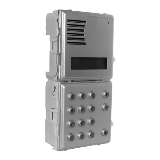
KOMBI CALLING MODULE WITH REPERTORY Ref. 1072/12 II ED. PERFORMANCE - STRUCTURE KOMBI CALLING MODULE WITH REPERTORY STRUCTURE Ref. 1072/12 The calling module with directory consists of the following parts: The 1072/12 calling module corresponds to 2 Kombi modules and is provided with back-lit 16x2 character display, built-in door unit and back-lit buttons. -
Page 28: Description Of Terminals And Connectors
Door opener code time band contact input Name/code display example: Mail key input Reference electrical ground URMET DOMUS Auxiliary device power Not used 1001 Alphabetic keyboard connector 1038/72 The following prompt will appear on the display if... -
Page 29: Direct Call To Concierge Switchboard
KOMBI CALLING MODULE WITH REPERTORY Ref. 1072/12 II ED. OPERATION CALLS TO USERS BY SELECTING THE CODE DOOR OPENER CODES Press the button before entering each door opener code. Select NAME Symbol “∗” will appear on the display when entering the code for each ↑... -
Page 30: Programming
KOMBI CALLING MODULE WITH REPERTORY Ref. 1072/12 II ED. PROGRAMMING The main menu will appear on the display when programming mode is PROGRAMMING accessed: The module can be programmed in three ways when the system is Main Menu powered: via external keyboard ref. 1032/65 (recommended method); ↓... - Page 31 KOMBI CALLING MODULE WITH REPERTORY Ref. 1072/12 II ED. PROGRAMMING EDITION BUSY TIME The module can be confi gured as a 1st edition or 2nd edition device. The busy time is split into two sub-menus. The module must be programmed as 1st edition if there is even The following message will appear on the display: only one 1st edition device in the system (when replacing parts in old systems).
- Page 32 KOMBI CALLING MODULE WITH REPERTORY Ref. 1072/12 II ED. PROGRAMMING DOOR OPENER CODES Enter the numeric or alphanumeric code formed by a variable number of digits from 1 to 4 and press to confi rm. Press to correct. The eight generic door opener codes can be stored in sequence. Press for longer than three seconds to go back to the previous The following message will appear on the display:...
- Page 33 KOMBI CALLING MODULE WITH REPERTORY Ref. 1072/12 II ED. PROGRAMMING • Change the name: after changing the user code, a form similar to B: Door phone programming procedure the name enter form will appear. Edit the name and press Go to the fi rst booked user, hold the button pressed and lift the confi...
-
Page 34: Default Settings
DISPLAY CONTRAST REGULATION The B-BUS 2nd edition program can be downloaded free of charge from the Urmet Domus web site (http://www.urmetdomus.com). The display contrast is set at the factory and will not need to be adjusted in most installations. -
Page 35: Installation
KOMBI CALLING MODULE WITH REPERTORY Ref. 1072/12 II ED. INSTALLATION - ACCESSORY INSTALLATION WALL-MOUNTED VERSION WITH CASE AND HOOD INSTALLATION The case and hood is provided with frame and module holder. The The calling module Ref. 1072/12 with repertory can be used alone available models and the dimensions are shown in “Technical product or in combination with camera unit and/or alphabet keyboard add-on manual - door phone and video door phone systems - MT101-013”... - Page 36 KOMBI CALLING MODULE WITH REPERTORY Ref. 1072/12 II ED. ACCESSORY INSTALLATION Fasten the lower side of the fl ush-mounting box using the two screws EXAMPLES OF MODULAR CONSTRUCTIONS provided for this purpose so that the head projects from the wall by approximately 2 mm to prevent distortion and compensate for the Recommended calling module constructions are shown below.
- Page 37 K-STEEL CALLING MODULE WITH REPERTORY Ref. 1072/14 II ED. PERFORMANCE - STRUCTURE K-STEEL CALLING MODULE WITH REPERTORY STRUCTURE Ref. 1072/14 The calling module with directory consists of the following parts: The 1072/14 calling module corresponds to 2 K-Steel modules and is provided with back-lit 16x2 character display, built-in door unit and back-lit buttons.
- Page 38 The apartment door phone will ring for approximately 3 seconds. Hold pressed to send up to three consecutive calls. MS1 terminal board Name/code display example: Door opener code time band contact input Mail key input URMET DOMUS Reference electrical ground 1001 Auxiliary device power Not used Alphabetic keyboard connector 1038/73...
- Page 39 K-STEEL CALLING MODULE WITH REPERTORY Ref. 1072/14 II ED. OPERATION CALLS TO USERS BY SELECTING THE CODE DOOR OPENER CODES Press the button before entering each door opener code. Select NAME Symbol “∗” will appear on the display when entering the code for each ↑...
- Page 40 K-STEEL CALLING MODULE WITH REPERTORY Ref. 1072/14 II ED. PROGRAMMING The main menu will appear on the display when programming mode is PROGRAMMING accessed: The module can be programmed in three ways when the system is Main Menu powered: via external keyboard 1032/65 (recommended method); ↓...
- Page 41 K-STEEL CALLING MODULE WITH REPERTORY Ref. 1072/14 II ED. PROGRAMMING EDITION BUSY TIME The module can be confi gured as a 1st edition or 2nd edition device. The busy time is split into two sub-menus. The module must be programmed as 1st edition if there is even The following message will appear on the display: only one 1st edition device in the system (when replacing parts in old systems).
- Page 42 K-STEEL CALLING MODULE WITH REPERTORY Ref. 1072/14 II ED. PROGRAMMING DOOR OPENER CODES Enter the numeric or alphanumeric code formed by a variable number of digits from 1 to 4 and press to confi rm. Press to correct. The eight generic door opener codes can be stored in sequence. Press for longer than three seconds to go back to the previous The following message will appear on the display:...
- Page 43 K-STEEL CALLING MODULE WITH REPERTORY Ref. 1072/14 II ED. PROGRAMMING • Change the user door opener code: a form similar to that for entering Refer to the supplied sheet to remember the code/button association door opener codes will appear after editing the name. Edit the code sequence.
- Page 44 Use a screwdriver to adjust the trimmers if required. The B-BUS PC program can be used for simple and fast module programming. The B-BUS 2nd edition program can be downloaded free of charge from the Urmet Domus web site (http://www.urmetdomus.com). DISPLAY CONTRAST REGULATION Minimum PC requirements are: •...
- Page 45 K-STEEL CALLING MODULE WITH REPERTORY Ref. 1072/14 II ED. INSTALLATION INSTALLATION Calling module with repertory Ref. 1072/14 can be used alone or n° 7 M3 in combination with a camera unit and/or alphabet keyboard add-on Ref. 1038/73. Examples of modular constructions using 2 or 3 module holder frames with respective fl...
- Page 46 K-STEEL CALLING MODULE WITH REPERTORY Ref. 1072/14 II ED. INSTALLATION WALL-MOUNTED VERSION WITH CASE AND HOOD Cases and hoods protect the calling module from the weather and may be used for installation on walls without fl ush-mounted parts. The case is provided with module holder frame. The available models and the dimensions of cases and frames are shown in “Technical product manual - door phone and video door phone systems - MT101-013”...
- Page 47 K-STEEL CALLING MODULE WITH REPERTORY Ref. 1072/14 II ED. INSTALLATION EXAMPLES OF MODULAR CONSTRUCTIONS Ref. Ref. Ref. 1755/30A 1755/30A 1755/30A Ref. Ref. Ref. 1072/14 1072/14 1072/14 Ref. 1038/73 Ref. Ref. 1072/14 1072/14 Ref. 1038/73 Ref. 1038/73 Ref. 1155/62 Ref. 1155/61 Ref.
- Page 48 II ED. −−−− sec.2 MT124-013B...
- Page 49 SECTION 3 II ED. DIGITISERS WITH BUILT-IN DOOR UNIT PANEL MODELS Download from www.urmetdomus.com Technical Manuals area MT124-013B_sec.3.pdf sec.3 −−−− MT124-013B...
- Page 50 II ED. −−−− sec.3 MT124-013B...
- Page 51 SECTION 3 CONTENTS II ED. BIBUS II^ Ed. VOP SYSTEM Sec. Pag. DIGITISERS WITH BUILT-IN DOOR UNIT AND PANEL MODELS LOUDSPEAKING UNIT WITH BUILT-IN DIGITALIZER DEVICE Ref. 1072/19A PERFORMANCE....................................3 ....STRUCTURE ......................................3 ....DESCRIPTION OF TERMINAL BOARDS..............................3 ....TECHNICAL SPECIFICATIONS ................................3 ....CONNECTIONS .....................................3 ....
- Page 52 SECTION 3 CONTENTS II ED. BIBUS II^ Ed. VOP SYSTEM KOMBI PUSH BUTTON PANEL Mod. 825 MODULES ARRANGED FOR DOOR UNIT WITH DIGITIZER......................3 ..... Description of terminals ..................................3 ..... CAMERA UNIT MODULES FOR KOMBI PUSH-BUTTON PANELS.....................3 ..... B&w camera unit module..................................3 ..... Colour door camera module ................................3 .....
-
Page 53: Performance
Simplifi ed programming dip-switch. PERFORMANCE Programming adapter connector Ref. 1072/60. Simplifi ed programming button and LED. • Can be installed with Urmet Domus 725 two-row push-button Microphone. Microphone volume adjustment. panels. • Can be installed with Urmet Domus KOMBI push-button panels. -
Page 54: Connections
LOUDSPEAKING UNIT WITH BUILT-IN DIGITALIZER DEVICE Ref. 1072/19A II ED. CONNECTIONS - FUNCTION - PROGRAMMING CONNECTIONS PROGRAMMING IMPORTANT: Observe the instructions contained in section 1 for In simple systems, the door unit can be programmed by wiring and maximum distances. means of the LED button and the two dip-switches without the help of external devices. - Page 55 LOUDSPEAKING UNIT WITH BUILT-IN DIGITALIZER DEVICE Ref. 1072/19A II ED. PROGRAMMING Once a code is programmed, press button ↵ to automatically program STATION NUMBER (ID) call code xyzw+1 on button nm+1. For example, the calling sequence C1000P01 ↵ ↵ ↵ will program code 1000 on button 01, code 1002 A number from 1 to 12 is assigned to each main calling station.
-
Page 56: Simplified Programming
LOUDSPEAKING UNIT WITH BUILT-IN DIGITALIZER DEVICE Ref. 1072/19A II ED. PROGRAMMING 3. A beep will be heard after 30 seconds from last pressing a user STATION NUMBER (ID) button (end of booking). 4. Leave the adapter 1072/60 in the digitiser and go to the apartments The two dip-switches determine the main station number as shown in to program the door phones. -
Page 57: Default Programming
LOUDSPEAKING UNIT WITH BUILT-IN DIGITALIZER DEVICE Ref. 1072/19A PROGRAMMING II ED. LOUDSPEAKING UNIT WITH INTEGRATED DIGITALIZER - K-STEEL Ref. 1072/5 PERFORMANCE - STRUCTURE ASSOCIATING 2/3 DOOR PHONES IN PARALLEL IN 2ND LOUDSPEAKING UNIT WITH INTEGRATED EDITION SYSTEMS USING THE SIMPLIFIED PROGRAMMING DIGITALIZER - K-STEEL Ref. -
Page 58: Description Of Terminal Boards
LOUDSPEAKING UNIT WITH INTEGRATED DIGITALIZER - K-STEEL Ref. 1072/5 II ED. DESCRIPTION OF TERMINAL BOARDS - TECHNICAL SPECIFICATIONS - CONNECTIONS FUNCTION - PROGRAMMING 1) Programming connector (PROG) for adapter 1072/60. FUNCTION 2) Terminals for connecting two buttons provided (1-2-C) and respective back-lighting (0~-12~). - Page 59 LOUDSPEAKING UNIT WITH INTEGRATED DIGITALIZER - K-STEEL Ref. 1072/5 II ED. PROGRAMMING Letter “M” identifi es the type of system: MINIMUM CONVERSATION TIME (BUSY) press M1 ↵ to program 1st edition press M2 ↵ to program 2nd edition When a user is called and answers the door phone, all other call stations will be busy for the minimum programmed conversation time.
- Page 60 LOUDSPEAKING UNIT WITH INTEGRATED DIGITALIZER - K-STEEL Ref. 1072/5 II ED. PROGRAMMING Refer to the supplied sheet to remember the code/button association ASSOCIATING 2 DOOR PHONES IN PARALLEL IN 1ST EDITION sequence. SYSTEMS USING THE PROGRAMMING ADAPTER SEQUENZA DI ASSOCIAZIONE ASSOCIATION SEQUENCE To install two door phones in one apartment and make them both ring when a call is received, press the button related to the user twice with...
- Page 61 LOUDSPEAKING UNIT WITH INTEGRATED DIGITALIZER - K-STEEL Ref. 1072/5 II ED. VOLUME REGULATION - TROUBLESHOOTING button pressed for the time to be programmed (up to 30 s). The door VOLUME REGULATION unit will acquire the value and a confi rmation beep will be heard. Press the programming button to return to normal operation.
- Page 62 16-PUSHBUTTON EXPANSION MODULE Ref. 1038/17 II ED. DESCRIPTION OF TERMINALS - TECHNICAL SPECIFICATIONS Mod. DOMUS AURA 16-PUSHBUTTON EXPANSION MODULE Ref. 1038/17 For 20 button push-button panel only: Ref. 1110/220 (door phone) and Ref. 1710/220 (video door phone). OUTPUT INPUT OUTPUT INPUT Other expansion...
- Page 63 ADAPTER DEVICE FOR TV CAMERA Ref. 1742/13A CAMERA UNIT ASSEMBLY INSTRUCTIONS Mod. 725 II ED. INSTRUCTIONS FOR ASSEMBLY ON TV CAMERA MODULE WITH ADJUSTABLE CCD CAMERA Ref. 825/70 AND Ref. 1810/70 ADAPTER DEVICE FOR TV CAMERA INSTRUCTIONS ASSEMBLY Ref. 1742/13A CAMERA MODULE WITH ADJUSTABLE CCD CAMERA Ref.
- Page 64 PANELS WITH ANODIZED ALUMINIUM FRONT PLATE Mod. 725 II ED. CAMERA UNIT PANELS WITH ANODIZED ALUMINIUM FRONT PLATE Mod. 725 WHITE COLOUR BLACK COLOUR 725 panel with aluminium front plate is modular. Various door phone and video door phone confi gurations can be made by arranging panels and camera units where relevant to obtain the required capacity.
- Page 65 PANELS WITH ANODIZED ALUMINIUM FRONT PLATE Mod. 725 II ED. PRODUCT LIST - INSTALLATION PRODUCT LIST INSTALLATION Pushbutton with two rows of buttons and door unit set-up Fit the adhesive rubbers on the door unit and digitiser; With 4 buttons Ref.
- Page 66 PANELS WITH ANODIZED ALUMINIUM FRONT PLATE Mod. 725 DOOR PHONE SYSTEMS II ED. DIMENSIONS 194 mm 399 mm 604 mm 2 rows 4 rows 6 rows 205 mm 410 mm 615 mm 2 rows 4 rows 6 rows Dimension Height (mm) Flush H1 Front H2 Number of buttons on panel...
- Page 67 PANELS WITH ANODIZED ALUMINIUM FRONT PLATE Mod. 725 DOOR PHONE SYSTEMS II ED. EXAMPLES OF MODULAR CONSTRUCTIONS WITH VARIOUS CAPACITIES Door unit with digitiser 1072/19A 1072/19A 1072/19A 1072/19A 16-users expansion module Buttons set up for door unit 725/204 725/206 725/208 725/210 Buttons not set up for door unit Wall mounting box with hood...
- Page 68 PANELS WITH ANODIZED ALUMINIUM FRONT PLATE Mod. 725 DOOR PHONE SYSTEMS II ED. EXAMPLES OF MODULAR CONSTRUCTIONS WITH VARIOUS CAPACITIES Door unit with digitiser 1072/19A 1072/19A 1072/19A 16-users expansion module 2 x 1038/17 2 x 1038/17 3 x 1038/17 Buttons set up for door unit 725/218 725/220 725/222...
- Page 69 PANELS WITH ANODIZED ALUMINIUM FRONT PLATE Mod. 725 VIDEO DOOR PHONE SYSTEMS II ED. DIMENSION 53 mm 194 mm 399 mm 604 mm 2 rows 4 rows 6 rows 205 mm 410 mm 615 mm 2 rows 4 rows 6 rows Dimension Height (mm) Flush H1...
- Page 70 PANELS WITH ANODIZED ALUMINIUM FRONT PLATE Mod. 725 VIDEO DOOR PHONE SYSTEMS II ED. EXAMPLES OF MODULAR CONSTRUCTIONS WITH VARIOUS CAPACITIES Door unit with digitiser 1072/19A 1072/19A 1072/19A 1072/19A 16-users expansion module Camera 725/600 725/600 725/600 725/600 Adapter for TV camera 1742/13A 1742/13A 1742/13A...
- Page 71 PANELS WITH ANODIZED ALUMINIUM FRONT PLATE Mod. 725 VIDEO DOOR PHONE SYSTEMS II ED. EXAMPLES OF MODULAR CONSTRUCTIONS WITH VARIOUS CAPACITIES Door unit with digitiser 1072/19A 1072/19A 1072/19A 16-users expansion module 1 x 1038/17 1 x 1038/17 1 x 1038/17 Camera 725/600 725/600...
- Page 72 PANELS WITH ANODIZED ALUMINIUM FRONT PLATE Mod. 725 VIDEO DOOR PHONE SYSTEMS II ED. EXAMPLES OF MODULAR CONSTRUCTIONS WITH VARIOUS CAPACITIES Door unit with digitiser 1072/19A 1072/19A 16-users expansion module 3 x 1038/17 4 x 1038/17 Camera 725/600 725/600 Adapter for TV camera 1742/13A 1742/13A Front unit...
- Page 73 KOMBI PUSH BUTTON PANEL Mod. 825 II ED. MODULES ARRANGED FOR DOOR UNIT WITH DIGITIZER CAMERA UNIT MODULES FOR KOMBI PUSH-BUTTON PANELS KOMBI PUSH BUTTON PANEL Mod. 825 CAMERA UNIT MODULES FOR KOMBI PUSH- BUTTON PANELS The following camera units can be used in Bibus VOP video door phone systems •...
- Page 74 KOMBI PUSH BUTTON PANEL Mod. 825 II ED. PRODUCT LIST -INSTALLATION PRODUCT LIST INSTALLATION Push button and repertory modules You are advised to install the modules at the heights shown below according to the required system confi guration. With 1 key Ref.
- Page 75 KOMBI PUSH BUTTON PANEL Mod. 825 II ED. INSTALLATION Apply the door unit and digitiser to the installation module. Insert the modules in the frame and make the electrical connections. Close the panel and fasten the upper head screw. sec.3 −−−− MT124-013B...
- Page 76 KOMBI PUSH BUTTON PANEL Mod. 825 II ED. DIMENSION FLUSH MOUNTED 45 mm 118 mm 378 mm 126 mm 252 mm Note: H1= 204, 294, 384 indicates fl ush mounting height and H2= 213, 303, 393 indicates to total height relative to 2, 3 and 4 module versions.
- Page 77 KOMBI PUSH BUTTON PANEL Mod. 825 DOOR PHONE SYSTEMS II ED. EXAMPLES OF MODULAR CONSTRUCTIONS WITH VARIOUS CAPACITIES (#): alternatives ∗ ): alternatives Door unit with digitiser 1072/19A 1072/19A 1072/19A Door unit modules 825/16 825/17 825/15 Button modules Repertory module 825/203 16-user expansion module ∗...
- Page 78 KOMBI PUSH BUTTON PANEL Mod. 825 DOOR PHONE SYSTEMS II ED. EXAMPLES OF MODULAR CONSTRUCTIONS WITH VARIOUS CAPACITIES (#): alternatives ∗ ): alternatives Door unit with digitiser 1072/19A 1072/19A 1072/19A Door unit modules 825/17 825/15 825/15 Button modules Repertory module 2 x 825/204 1 x 825/203 - 1 x 825/204 2 x 825/204...
- Page 79 KOMBI PUSH BUTTON PANEL Mod. 825 DOOR PHONE SYSTEMS II ED. EXAMPLES OF MODULAR CONSTRUCTIONS WITH VARIOUS CAPACITIES (#): alternatives ∗ ): alternatives Door unit with digitiser 1072/19A 1072/19A 1072/19A Door unit modules 825/15 825/15 825/16 Button modules Repertory module 1 x 825/203 - 3 x 825/204 4 x 825/204 4 x 825/204...
- Page 80 KOMBI PUSH BUTTON PANEL Mod. 825 DOOR PHONE SYSTEMS II ED. EXAMPLES OF MODULAR CONSTRUCTIONS WITH VARIOUS CAPACITIES (#): alternatives ∗ ): alternatives Door unit with digitiser 1072/19A 1072/19A 1072/19A Door unit modules 825/16 825/17 825/15 Button modules Repertory module 6 x 825/204 6 x 825/204 5 x 825/203 - 1 x 825/204...
- Page 81 KOMBI PUSH BUTTON PANEL Mod. 825 DOOR PHONE SYSTEMS II ED. EXAMPLES OF MODULAR CONSTRUCTIONS WITH VARIOUS CAPACITIES (#): alternatives ∗ ): alternatives Door unit with digitiser 1072/19A 1072/19A 1072/19A Door unit modules 825/17 825/15 825/15 Button modules Repertory module 6 x 825/204 825/5 1 x 825/203 - 6 x 825/204...
- Page 82 KOMBI PUSH BUTTON PANEL Mod. 825 B&W VIDEO DOOR PHONE SYSTEMS II ED. EXAMPLES OF MODULAR CONSTRUCTIONS WITH VARIOUS CAPACITIES (#): alternatives ∗ ): alternatives Camera unit module 825/70 825/70 825/70 Adapter for TV camera 1742/13A 1742/13A 1742/13A Door unit with digitiser 1072/19A 1072/19A 1072/19A...
- Page 83 KOMBI PUSH BUTTON PANEL Mod. 825 B&W VIDEO DOOR PHONE SYSTEMS II ED. EXAMPLES OF MODULAR CONSTRUCTIONS WITH VARIOUS CAPACITIES (#): alternatives ∗ ): alternatives Camera unit module 825/70 825/70 825/70 Adapter for TV camera 1742/13A 1742/13A 1742/13A Door unit with digitiser 1072/19A 1072/19A 1072/19A...
- Page 84 KOMBI PUSH BUTTON PANEL Mod. 825 B&W VIDEO DOOR PHONE SYSTEMS II ED. EXAMPLES OF MODULAR CONSTRUCTIONS WITH VARIOUS CAPACITIES (#): alternatives ∗ ): alternatives Camera unit module 825/70 825/70 825/70 Adapter for TV camera 1742/13A 1742/13A 1742/13A Door unit with digitiser 1072/19A 1072/19A 1072/19A...
- Page 85 KOMBI PUSH BUTTON PANEL Mod. 825 B&W VIDEO DOOR PHONE SYSTEMS II ED. EXAMPLES OF MODULAR CONSTRUCTIONS WITH VARIOUS CAPACITIES (#): alternatives ∗ ): alternatives Camera unit module 825/70 825/70 825/70 Adapter for TV camera 1742/13A 1742/13A 1742/13A Door unit with digitiser 1072/19A 1072/19A 1072/19A...
- Page 86 KOMBI PUSH BUTTON PANEL Mod. 825 COLOUR VIDEO DOOR PHONE SYSTEMS II ED. EXAMPLES OF MODULAR CONSTRUCTIONS WITH VARIOUS CAPACITIES (#): alternatives ∗ ): alternatives Camera unit module 1855/70 1855/70 1855/70 Lighting module 1855/50 1855/50 1855/50 adapter for TV camera 1742/13A 1742/13A 1742/13A...
- Page 87 KOMBI PUSH BUTTON PANEL Mod. 825 COLOUR VIDEO DOOR PHONE SYSTEMS II ED. EXAMPLES OF MODULAR CONSTRUCTIONS WITH VARIOUS CAPACITIES (#): alternatives ∗ ): alternatives Camera unit module 1855/70 1855/70 1855/70 Lighting module 1855/50 1855/50 1855/50 adapter for TV camera 1742/13A 1742/13A 1742/13A...
- Page 88 KOMBI PUSH BUTTON PANEL Mod. 825 COLOUR VIDEO DOOR PHONE SYSTEMS II ED. EXAMPLES OF MODULAR CONSTRUCTIONS WITH VARIOUS CAPACITIES (#): alternatives ∗ ): alternatives Camera unit module 1855/70 1855/70 1855/70 Lighting module 1855/50 1855/50 1855/50 adapter for TV camera 1742/13A 1742/13A 1742/13A...
- Page 89 DOMUS-AURA ARTISTIC 2-ROW PUSH-BUTTON PANEL Mod. 1110 e Mod. 1710 II ED. ADJUSTABLE CCD CAMERA UNIT FOR ARTISTIC PUSH-BUTTON PANELS Ref. 1810/70 DOMUS AURA PANEL INSTALLATION DOMUS-AURA ARTISTIC 2-ROW PUSH- DOMUS AURA PANEL INSTALLATION BUTTON PANEL Mod. 1110 (door phone) AND •...
- Page 90 DOMUS-AURA ARTISTIC 2-ROW PUSH-BUTTON PANEL Mod. 1110 e Mod. 1710 II ED. DIMENSION EXAMPLES OF MODULAR CONSTRUCTIONS WITH VARIOUS CAPACITIES ARTISTIC DOOR PHONE PUSH BUTTON PANEL CODE DESCRIPTION Front Embedding dimensions (mm) box dimensions (mm) Artistic door phone Width Height Width Height Depth...
- Page 91 DOMUS-AURA ARTISTIC 2-ROW PUSH-BUTTON PANEL Mod. 1110 e Mod. 1710 II ED. DIMENSION EXAMPLES OF MODULAR CONSTRUCTIONS WITH VARIOUS CAPACITIES ARTISTIC VIDEO DOOR PHONE PUSH BUTTON PANEL CODE DESCRIPTION Front Embedding dimensions (mm) box dimensions (mm) Artistic door phone Width Height Width Height...
- Page 92 K-STEEL MODULAR VANDAL-PROOF PANEL Mod. 1155 - Mod. 1755 II ED. DOOR CAMERA MODULE FOR K-STEEL VANDAL-PROOF PANEL PRODUCT LIST - INSTALLATION K-STEEL MODULAR VANDAL-PROOF PANEL PRODUCT LIST Mod. 1155 - Mod. 1755 Galvanized steel back boxes For 1 module Ref.
- Page 93 K-STEEL MODULAR VANDAL-PROOF PANEL Mod. 1155 - Mod. 1755 II ED. INSTALLATION n° 4 M4 x 16 max. 6 mm n° 4 M3 x 10 In the case of module installation with several fl ush-mounting boxes joined together, align the modules using a frame alignment shim before fastening the frame.
- Page 94 K-STEEL MODULAR VANDAL-PROOF PANEL Mod. 1155 - Mod. 1755 DOOR PHONE SYSTEMS - VIDEO DOOR PHONE SYSTEMS II ED. DIMENSIONS 138 mm 287 mm 435 mm 148 mm 296 mm 444 mm Note: H1= 139, 256, 376, 522 indicates flush mounting height and H2= 148, 266, 384, 532 indicates to total height relative to 1, 2, 3 and 4 module versions.
- Page 95 K-STEEL MODULAR VANDAL-PROOF PANEL Mod. 1155 - Mod. 1755 DOOR PHONE SYSTEMS II ED. EXAMPLES OF MODULAR CONSTRUCTIONS WITH VARIOUS CAPACITIES (•) alternatives 1155/84 - 1155/87 (♦) alternatives 1155/85 - 1155/88 (∗) alternatives 1155/86 - 1155/89 (@) alternatives 1÷2 Door unit with digitiser 1072/5 1072/5 1072/5...
- Page 96 K-STEEL MODULAR VANDAL-PROOF PANEL Mod. 1155 - Mod. 1755 DOOR PHONE SYSTEMS II ED. EXAMPLES OF MODULAR CONSTRUCTIONS WITH VARIOUS CAPACITIES (•) alternatives 1155/84 - 1155/87 (♦) alternatives 1155/85 - 1155/88 (∗) alternatives 1155/86 - 1155/89 (@) alternatives Door unit with digitiser 1072/5 1072/5 1072/5...
- Page 97 K-STEEL MODULAR VANDAL-PROOF PANEL Mod. 1155 - Mod. 1755 DOOR PHONE SYSTEMS II ED. EXAMPLES OF MODULAR CONSTRUCTIONS WITH VARIOUS CAPACITIES (•) alternatives 1155/84 - 1155/87 (♦) alternatives 1155/85 - 1155/88 (∗) alternatives 1155/86 - 1155/89 (@) alternatives Door unit with digitiser 1072/5 1072/5 1072/5...
- Page 98 K-STEEL MODULAR VANDAL-PROOF PANEL Mod. 1155 - Mod. 1755 DOOR PHONE SYSTEMS II ED. EXAMPLES OF MODULAR CONSTRUCTIONS WITH VARIOUS CAPACITIES (•) alternatives 1155/84 - 1155/87 (♦) alternatives 1155/85 - 1155/88 (∗) alternatives 1155/86 - 1155/89 (@) alternatives Door unit with digitiser 1072/5 1072/5 1072/5...
- Page 99 K-STEEL MODULAR VANDAL-PROOF PANEL Mod. 1155 - Mod. 1755 DOOR PHONE SYSTEMS II ED. EXAMPLES OF MODULAR CONSTRUCTIONS WITH VARIOUS CAPACITIES (•) alternatives 1155/84 - 1155/87 (♦) alternatives 1155/85 - 1155/88 (∗) alternatives 1155/86 - 1155/89 (@) alternatives Door unit with digitiser 1072/5 1072/5 1072/5...
- Page 100 K-STEEL MODULAR VANDAL-PROOF PANEL Mod. 1155 - Mod. 1755 VIDEO DOOR PHONE SYSTEMS II ED. EXAMPLES OF MODULAR CONSTRUCTIONS WITH VARIOUS CAPACITIES (°) alternatives 1155/85 - 1155/88 (*) alternatives 1155/86 - 1155/89 (@) alternatives 1÷2 Door unit with digitiser 1072/5 1072/5 1072/5 1072/5...
- Page 101 K-STEEL MODULAR VANDAL-PROOF PANEL Mod. 1155 - Mod. 1755 VIDEO DOOR PHONE SYSTEMS II ED. EXAMPLES OF MODULAR CONSTRUCTIONS WITH VARIOUS CAPACITIES (°) alternatives 1155/85 - 1155/88 (*) alternatives 1155/86 - 1155/89 (@) alternatives Door unit with digitiser 1072/5 1072/5 1072/5 1072/5 16-user expansion module...
- Page 102 K-STEEL MODULAR VANDAL-PROOF PANEL Mod. 1155 - Mod. 1755 VIDEO DOOR PHONE SYSTEMS II ED. EXAMPLES OF MODULAR CONSTRUCTIONS WITH VARIOUS CAPACITIES (°) alternatives 1155/85 - 1155/88 (*) alternatives 1155/86 - 1155/89 (@) alternatives Door unit with digitiser 1072/5 1072/5 1072/5 16-user expansion module 1 x 1038/17...
- Page 103 K-STEEL MODULAR VANDAL-PROOF PANEL Mod. 1155 - Mod. 1755 VIDEO DOOR PHONE SYSTEMS II ED. EXAMPLES OF MODULAR CONSTRUCTIONS WITH VARIOUS CAPACITIES (°) alternatives 1155/85 - 1155/88 (*) alternatives 1155/86 - 1155/89 (@) alternatives Door unit with digitiser 1072/5 1072/5 1072/5 16-user expansion module 1 x 1038/17...
- Page 104 II ED. −−−− sec.3 MT124-013B...
- Page 105 SECTION 4 II ED. APARTMENT STATION Download from: www.urmetdomus.com Technical Manuals area MT124-013B_sec.4.pdf sec.4 −−−− MT124-013B...
- Page 106 II ED. −−−− sec.4 MT124-013B...
- Page 107 SECTION 4 CONTENTS II ED. BIBUS II^ Ed. VOP SYSTEM Sec. Pag. APARTMENT STATION CONCIERGE SWITCHBOARD Ref. 1072/41 PERFORMANCE....................................4 ....STRUCTURE ......................................4 ....DESCRIPTION OF TERMINALS ................................4 ....TECHNICAL SPECIFICATIONS ................................4 ....INSTALLATION ......................................4 ....SWITCHING ON AND OFF..................................4 ....Switchboard off ....................................4 ....
- Page 108 SECTION 4 CONTENTS II ED. BIBUS II^ Ed. VOP SYSTEM DESCRIPTION OF TERMINAL BOARDS..............................4 ..... TECHNICAL SPECIFICATIONS ................................4 ..... PROGRAMMING....................................4 ..... OPERATION ......................................4 ..... SUPPLEMENTARY THREE-TONE RINGING FOR BIBUS Ref. 1072/59 ..........4 ..... TABLE MOUNTING KIT WHITE COLOUR Ref. 1132/50 ................4 .....
-
Page 109: Concierge Switchboard Ref. 1072/41
CONCIERGE SWITCHBOARD Ref. 1072/41 II ED. PERFORMANCE - STRUCTURE CONCIERGE SWITCHBOARD Ref. 1072/41 STRUCTURE The switchboard consists of the following parts: The Bibus system concierge switchboard offers the following functions: • communication from and to door units with the possibility of storing unanswered calls;... -
Page 110: Description Of Terminals
CONCIERGE SWITCHBOARD Ref. 1072/41 II ED. DESCRIPTION OF TERMINALS - TECHNICAL SPECIFICATIONS INSTALLATION - SWITCHING ON AND OFF RETURNING TO NIGHT SERVICE DESCRIPTION OF TERMINALS The following will appear on the switchboard display: The following terminals are provided on the wiring junction box: 12 Vac power Night Service 12 Vac power... -
Page 111: Programming
CONCIERGE SWITCHBOARD Ref. 1072/41 II ED. PROGRAMMING PROGRAMMING Main Menu ↑↓ The switchboard can be programmed in three ways when the system Codes/Names is powered: Via external keyboard 1032/65 (recommended). Via built-in keyboard. Main Menu Via PC connection. ↑↓ Association PROGRAMMING VIA KEYBOARD 1032/65 Main Menu Programming mode is accessed automatically when the external... - Page 112 CONCIERGE SWITCHBOARD Ref. 1072/41 II ED. PROGRAMMING Language buttons to select and button to confi rm. The system will automatically return to the main menu after a The following will appear on the display: confi rmation tone. Language Busy time (minimum conversation time) ↑↓...
- Page 113 CONCIERGE SWITCHBOARD Ref. 1072/41 II ED. PROGRAMMING Enter data Search by position This submenu is used to add user codes and respective names. This submenu is used to edit a user code or name of a position in the table or delete a record. The following will appear on the display: First edition only: the call station to which the code was previously associated will be required: Position:...
-
Page 114: Default Programming
The B-BUS program (version 2.0 or higher) can be downloaded If required, adjust trimmer RV4 in the switchboard with a screwdriver. from the URMET DOMUS web site (http://www.urmetdomus.com) free of charge. −−−− sec.4 MT124-013B... -
Page 115: Calling Indoor Sets Users
The following message will appear if the user does not answer within Example of name/code display: the programmed off-hook waiting time: URMET DOMUS User 1001 does not reply The code will not be displayed in fi rst edition systems. -
Page 116: Call Reception (Second Edition)
CONCIERGE SWITCHBOARD Ref. 1072/41 II ED. CONCIERGE SERVICE Raise the handset to start communication with the indoor set. LED (18) CONCIERGE SERVICE will light up and the following message will appear: Concierge service is offered when the switchboard is in Day mode. CONVERSATION The following will appear on the display: ACTIVE WITH I.S. -
Page 117: Door Opener
CONCIERGE SWITCHBOARD Ref. 1072/41 II ED. DOOR OPENER - BUSY FUNCTION - SETTING DATE AND TIME - ADDITIONAL INFORMATION BUSY TIME BEFORE THE CALLED USER PICKS UP Press to pick up the call on hold. The following will appear on the This is the maximum time available for the user to pick up the handset display: after the ring and/or press the door opener button without loosing the... -
Page 118: Basic Door Phone Ref. 1172/31 - Comfort Door Phone Ref. 1172/32
BASIC DOOR PHONE Ref. 1172/31 - COMFORT DOOR PHONE Ref. 1172/32 II ED. PERFORMANCE - STRUCTURE - DESCRIPTION OF TERMINAL BOARDS TECHNICAL SPECIFICATIONS Base BASIC DOOR PHONE Ref. 1172/31 Hood COMFORT DOOR PHONE Ref. 1172/32 Call speaker compartment Concierge call button Staircase light button Open door LED Open door button... -
Page 119: Programming
BASIC DOOR PHONE Ref. 1172/31 - COMFORT DOOR PHONE Ref. 1172/32 PROGRAMMING - OPERATION II ED. DOOR PHONE WITH MULTIPLE RINGER TONES AND MUTE FUNCTION Ref. 1172/35 PERFORMANCE - STRUCTURE PROGRAMMING DOOR PHONE WITH MULTIPLE RINGER TONES AND MUTE FUNCTION Ref. 1172/35 Refer to the “Programming”... -
Page 120: Description Of Terminal Boards
DOOR PHONE WITH MULTIPLE RINGER TONES AND MUTE FUNCTION Ref. 1172/35 II ED. DESCRIPTION OF TERMINAL BOARDS - TECHNICAL SPECIFICATIONS PROGRAMMING - OPERATION Two possibilities may occur: DESCRIPTION OF TERMINAL BOARDS 1. the concierge answers within 10s or the door phone line is free: a conversation with the concierge is established;... -
Page 121: Concierge Door Phone Ref. 1172/33
90% RH at 30°C PERFORMANCE Supplementary ringer control: V max=30Vdc • Operation in 2nd Edition systems only (contact the Urmet Domus I max=40mAdc Customer Service for replacing parts in old systems). • Conversation privacy function (single integrated decoder) • Two-tone door phone call. -
Page 122: Door Phone With Multiple Ringers Ref. 1172/34
DOOR PHONE WITH MULTIPLE RINGERS Ref. 1172/34 II ED. PERFORMANCE - STRUCTURE - DESCRIPTION OF TERMINAL BOARDS TECHNICAL SPECIFICATIONS - PROGRAMMING - OPERATION DOOR PHONE WITH MULTIPLE RINGERS DESCRIPTION OF TERMINAL BOARDS Ref. 1172/34 bus connection (not polarised) bus connection (not polarised) fl... - Page 123 SUPPLEMENTARY THREE-TONE RINGING FOR BIBUS Ref. 1072/59 II ED. 1. the concierge answers within 10s or the door phone line is free: a SUPPLEMENTARY THREE-TONE RINGING FOR conversation with the concierge is established. BIBUS Ref. 1072/59 2. the concierge does not answer within 10s or the line is busy: the door phone LED will fl...
- Page 124 TABLE MOUNTING KIT WHITE COLOUR Ref. 1132/50 II ED. TABLE MOUNTING KIT WHITE COLOUR Ref. 1132/50 Use the dedicated transformation kit Ref. 1132/50 to set up the door phone table mounted version. Operations to be carried up for assembly: • Insert the 4 self-adhesive rubber pads provided under the base of the table support.
-
Page 125: Sentry+ Video Door Phone Mod. 1704
SENTRY+ VIDEO DOOR PHONE Mod. 1704 II ED. SPECIFICATIONS - SENTRY+ BRACKETS FOR BIBUS II^ ED. VOP Ref. 1704/954 • two potentiometers for adjusting picture brightness ( SENTRY+ VIDEO DOOR PHONE Mod. 1704 ) and contrast • one switch for three-position call tone volume adjustment ( ) (minimum, medium and maximum volume). -
Page 126: Bracket Terminals
SENTRY+ VIDEO DOOR PHONE Mod. 1704 II ED. INSTALLATION BRACKET TERMINALS Ref. 1704/60 VPI: VOP signal input terminals Ref. 1704/954 VPU: VOP signal output terminals (for in-out or parallel monitor con- nection) Ref. 1704/1A L1, L2: Door phone bus C1, C2: Floor call Important: Never fi... -
Page 127: Programming
SENTRY+ VIDEO DOOR PHONE Mod. 1704 II ED. PROGRAMMING NOTE: Consider the following correspondence between terminals when AUTO-ON using the table mounting kit in Bibus 2nd edition VOP systems: Video or audio/video auto-on from the MAIN station 1 is possible. With Table mounting kit Sentry+ bracket the door phone standing by, press the concierge call button without... -
Page 128: Winflat+ Video Door Phone Ref. 1202/1A
WINFLAT+ VIDEO DOOR PHONE Ref. 1202/1A II ED. TECHNICAL SPECIFICATIONS WINFLAT+ VIDEO DOOR PHONE Ref. 1202/1A 16 ÷ 18.5 Vdc Power voltage: Working power: max. 6.5 W CCIR version: Vertical frequency: 50 Hz ± 2 Hz Horizontal frequency: 15625 ± 300 Hz Video signal: 1 Vpp 75 W nominal 1 Vpp. -
Page 129: Winspot+ Video Door Phone Ref. 1855/11A
WINSPOT+ VIDEO DOOR PHONE Ref. 1855/11A II ED. TECHNICAL SPECIFICATIONS WINSPOT+ VIDEO DOOR PHONE Ref. 1855/11A 16 ÷ 18.5 Vdc Power voltage: Working power: max. 6.5 W CCIR version: Vertical frequency: 50 Hz ± 2 Hz Horizontal frequency: 15625 ± 300 Hz Video signal: 1 Vpp 75 W nominal 1 Vpp -6 dB minimum... -
Page 130: Brackets For Winflat+ And Winspot+ Ref.1202/954
WINSPOT+ AND WINFLAT+ VIDEO DOORS PHONES II ED. BRACKETS FOR WINFLAT+ AND WINSPOT+ Ref.1202/954 - INSTALLATION BRACKETS FOR WINFLAT+ AND WINSPOT+ Bracket Ref. 1202/1A Ref.1202/954 Ref. 1855/11A Winfl at+ and Winspot+ video door phone are provided without fastening bracket which must be purchased separately. •... -
Page 131: Programming
WINSPOT+ VIDEO DOOR PHONE E WINFLAT+ II ED. PROGRAMMING Ref. 1202/92 Fig.1 Ref. 1202/954 Ref. 1202/1A Ref. 1855/11A Fig.2 PROGRAMMING PARALLEL MONITOR INSTALLATION A confi guration of up to two video door phones in parallel can be The procedure for programming video door phone user codes is the same obtained without the addition of local power units (refer to the VOP as for Bibus 2nd edition door phones. -
Page 132: Scaitel Video Module Ref. 1732/1
SCAITEL VIDEO MODULE Ref. 1732/1 II ED. SCAITEL VIDEO MODULE Ref. 1732/1 VIDEO MODULE BRACKET Ref. 1732/957 Switchboard connection wire CN2 BRACKET TERMINALS The Scaitel video module Ref. 1732/1 has a 4” fl at screen monitor and can be used in combination with switchboards Ref. 1072/41 so that the operator can see visitors. - Page 133 SCAITEL VIDEO MODULE Ref. 1732/1 II ED. TABLE MOUNTED KIT FOR SCAITEL MONITOR Ref. 1732/56 TABLE MOUNTED KIT FOR SCAITEL MONITOR Ref. 1732/56 Use the tabletop transformation kit Ref. 1732/56. Proceed as follows: • Insert the four adhesive rubbers provided in the housings under the base of the table mounting stand.
- Page 134 II ED. −−−− sec.4 MT124-013B...
- Page 135 SECTION 5 II ED. COUPLERS POWER UNITS VARIOUS DEVICES Download from www.urmetdomus.com Technical Manuals area MT124-013B_sec.5.pdf sec.5 −−−− MT124-013B...
- Page 136 II ED. −−−− sec.5 MT124-013B...
- Page 137 SECTION 5 CONTENTS II ED. BIBUS II^ Ed. VOP SYSTEM Sez. Pag. COUPLERS POWER UNITS VARIOUS DEVICES BUS COUPLER WITH TRANSFORMER Ref. 1072/24 PERFORMANCE....................................5 ....DESCRIPTION OF TERMINALS, CONFIGURATIONS AND DISPLAYS....................5 ....TECHNICAL SPECIFICATIONS ................................5 ....Dimensions ......................................5 ....INSTALLATION AND CONFIGURATION ..............................5 ....Staircase light controller relay................................5 ....
- Page 138 SECTION 5 CONTENTS II ED. BIBUS II^ Ed. VOP SYSTEM SPECIAL DECODER Ref. 1072/80 PERFORMANCE....................................5 ..... STRUCTURE ......................................5 ..... TECHNICAL SPECIFICATIONS ................................5 ..... OPERATION IN 2ND EDITION SYSTEMS............................5 ..... OPERATION IN 1ST EDITION SYSTEMS ............................5 ..... PROGRAMMING....................................5 ..... Operating mode ....................................5 ..... Relay energising time ..................................5 .....
-
Page 139: Bus Coupler With Transformer Ref. 1072/24
BUS COUPLER WITH TRANSFORMER Ref. 1072/24 II ED. Relay contacts: 24 Vdc 1.2 A - 24 Vac 1.2 A BUS COUPLER WITH TRANSFORMER Ref. 1072/24 Protections: Temperature: -5°C +40°C Disconnect the mains power for at least 60 seconds to reset the power unit if the PTC trips due to overload or short-circuit. -
Page 140: Video Vop Power Unit Ref. 1074/20
VIDEO VOP POWER UNIT Ref. 1074/20 II ED. VIDEO VOP POWER UNIT Ref. 1074/20 DIMENSIONS Length: 180 mm (10 DIN modules) Width: 90 mm Height: 75 mm INSTALLATION AND CONFIGURATION The casing is suitable for fi tting on DIN bar and wall by means of screws and bolts;... -
Page 141: Extended Differential Video Signal Regenerator Ref. 1795/250
EXTENDED DIFFERENTIAL VIDEO SIGNAL REGENERATOR Ref. 1795/250 II ED. EXTENDED DIFFERENTIAL VIDEO SIGNAL INSTALLATION REGENERATOR Ref. 1795/250 The device may be fastened to the wall by means of the bracket provided or fi tted on a DIN bar. Lever as shown in the fi gure to access the connection terminals. The video signal regenerator ref. -
Page 142: Security Transformer Ref. 9000/230
Outputs: R2 out 0.65 A int. RL 0.02 A V2 0.02 A URMET DOMUS Ref. 9000/230 transformer is used to power Bibus Protection: with PTC thermal cutout (*) 2nd Edition locks in systems fi tting traditional push-button panels and Operating temperature -5°C ÷... - Page 143 VOP VIDEO DISTRIBUTOR Ref. 1795/40 II ED. VOP FLOOR VIDEO DISTRIBUTOR Ref. 1074/54 VOP VIDEO DISTRIBUTOR Ref. 1795/40 VOP FLOOR VIDEO DISTRIBUTOR Ref. 1074/54 The video distributor 1795/40 shares out the differential video signal from the main cameras on several riser columns (up to four). The 1074/54 distributor is used to share out the VOP video signal from the column to four video door phones.
- Page 144 PROGRAMMING KEYBOARD Ref. 1032/65 II ED. PROGRAMMING ADAPTER Ref. 1072/60 PROGRAMMING KEYBOARD Ref. 1032/65 PROGRAMMING ADAPTER Ref. 1072/60 Ref. 1032/65 The programming keyboard Ref. 1032/65 is used to program the following devices: • Bibus calling module Ref. 1072/12 mod. Kombi Sch.1072/60 •...
- Page 145 (Ref. 1032/65) or connection wire (Ref. 1072/57) connected to a Personal Computer where the B-Bus 2nd Edition software is installed (the software can be downloaded free of charge from the Urmet Domus web site at www.urmetdomus.com). sec.5 −−−− MT124-013B...
-
Page 146: Performance
SUPPLEMENTARY RELAY Ref. 788/5 II ED. SPECIAL DECODER Ref. 1072/80 PERFORMANCE - STRUCTURE SUPPLEMENTARY RELAY Ref. 788/5 SPECIAL DECODER Ref. 1072/80 The device Ref. 788/5 consists of a relay with two toggle contacts and is used to build Bibus 2nd Edition video door phone systems with PERFORMANCE several main video door phone units. -
Page 147: Operation In 2Nd Edition Systems
SPECIAL DECODER Ref. 1072/80 II ED. TECHNICAL SPECIFICATIONS - OPERATION IN 2ND EDITION SYSTEMS OPERATION IN 1ST EDITION SYSTEMS - INSTALLATION - PROGRAMMING Terminals L1, L2 are used to connect to the bus. Connect indifferently TECHNICAL SPECIFICATIONS either to the main station side bus or to the door phone side bus. The connection of the electrical load to be controlled is made by means L1, L2 consumption: of fi... -
Page 148: Programming Special Decoder Control From Door Phones And Calling Stations
SPECIAL DECODER Ref. 1072/80 II ED. 2nd EDITION SYSTEM PROGRAMMING EXAMPLES RELAY ENERGISING TIME “abcd” is any user code (either numeric or with letter prefi x from A to J or with letter suffi x from A to J). Example: C1001X1↵, C0032X1↵, C178HX1, CG192X1↵. The programming step is required for toggle operation only. -
Page 149: Bibus Pabx Interface Ref. 1072/67
SPECIAL DECODER Ref. 1072/80 II ED. BIBUS PABX INTERFACE Ref. 1072/67 PERFORMANCE - STRUCTURE (3) If the special decoder was previously programmed with codes BIBUS PABX INTERFACE Ref. 1072/67 in memory locations X3 and X4, reprogram these locations with the same value as cell X1 (or X2) to avoid undesired activation. -
Page 150: Description Of Terminal Boards
BIBUS PABX INTERFACE Ref. 1072/67 II ED. DESCRIPTION OF TERMINAL BOARDS - TECHNICAL SPECIFICATIONS OPERATION - INSTALLATION To remove the terminal boards, pull the upwards levering with a DESCRIPTION OF TERMINAL BOARDS screwdriver where needed (see fi gure). Bus connection on door phone side Bus connection on door phone side Floor call button Floor call button... - Page 151 BIBUS PABX INTERFACE Ref. 1072/67 PROGRAMMING AND DELETING - WIRING DIAGRAM II ED. POWER LINE PROTECTION DEVICE 230 Vac 4000VA Ref. 1332/85 PROGRAMMING AND DELETING POWER LINE PROTECTION DEVICE 230 Vac 4000VA Ref. 1332/85 The interface is equipped with a single integrated decoder. Consequently, the programming sequence is the same as that of a BiBus door phone.
-
Page 152: Installation
230V power line. power line protection device 230V 4000VA Ref.1332/85 upstream to The Urmet Domus protection device Ref. 1332/80 is equipped with a the power fi lter to ensure better system operation. re-arming thermal switch. -
Page 153: Dimensions
103 mm A specifi c multipolar wire for connecting both the door phone and the WIRING DIAGRAM video signal is offered by Urmet Domus for connecting column devices in Bibus 2nd edition VOP systems. Ref. 1332/80 Wire 1074/90 must be used to ensure video signal transmission to... - Page 154 II ED. −−−− sec.5 MT124-013B...
- Page 155 SECTION 6 II ED. INSTALLATION DIAGRAMS Basic diagrams for connecting a panel to door phones and video door phones in Bibus II^ ed. VOP systems are illustrated in this section. The complete collection of technical diagrams (including those this section) found www.urmetdomus.com web site in the CLUB IN area “Electrical Diagrams”.
- Page 156 II ED. −−−− sec.6 MT124-013B...
- Page 157 SECTION 6 CONTENTS BIBUS II^ Ed. VOP SYSTEM Diagram Sec. Pag. INSTALLATION DIAGRAMS DIAGRAM NOTES ....................................6 ....CONNECTION OF MAX. 50 DOOR PHONES TO 1 CONCIERGE SWITCHBOARD AND 1 CALLING MODULE WITH REPERTORY ....................SC124-0072A ....6 ....CONNECTION OF MAX. 50 DOOR PHONES TO 1 CONCIERGE SWITCHBOARD AND 1 TRADITIONAL PUSH-BUTTON PANEL WITH DOOR UNIT AND DIGITISER..............
- Page 158 SECTION 6 CONTENTS BIBUS II^ Ed. VOP SYSTEM Diagram Sec. Pag. CONNECTION OF MAX. 50 VIDEO DOOR PHONES TO 1 VIDEO DOOR UNIT WITH CALLING MODULE Example of in-out connection without video fl oor distributors................SV124-0230 ....6 ..... CONNECTION OF MAX. 50 VIDEO DOOR PHONES TO 1 VIDEO DOOR UNIT WITH TRADITIONAL PUSH-BUTTON PANEL WITH DOOR UNIT AND DIGITISER Example of in-out connection without video fl...
- Page 159 INSTALLATION DIAGRAMS DIAGRAM NOTES II ED. CU.008 - MINIMUM WIRE CROSS-SECTION AREAS CU.002 - Insert the connector (provided with product) to M/S socket FROM MASTER COUPLER TO ANY in only one of the bus couplers in the DEVICE CONNECTED ON MAIN SIDE system.
- Page 160 INSTALLATION DIAGRAMS DIAGRAM NOTES II ED. VD.007 = Floor call button. VU.006 - WIRE CROSS-SECTION AREA FROM BUS MASTER COUPLER TO ANY DEVICE CONNECTED ON MAIN STATION SIDE Distance Wires 0,75 0,75 L1, L2 ~0*, ~12* VU.002 - Follow the instructions FROM BUS COUPLER TO SECONDARY STATION provided with the product for fitting the camera.
- Page 161 INSTALLATION DIAGRAMS DIAGRAM NOTES II ED. VX.006 - See the instruction book provided with the product for fitting the accessory in the device. VX.008 - Connect the devices to a filter and power line protection device. Ref.1332/85 Ref.1332/86 PROTECTION FILTER NEUTRAL EARTH LIVE...
- Page 162 CONNECTION OF MAX. 50 DOOR PHONES TO 1 CONCIERGE SWITCHBOARD AND 1 CALLING MODULE WITH REPERTORY II ED. SC124-0072A DEVICES n. 50 (*) Basic door phones Ref. 1172/31 Comfort door phones Ref. 1172/32 Concierge door phones Ref. 1172/33 Door phone with multiple ringer tones Ref.
- Page 163 CONNECTION OF MAX. 50 DOOR PHONES TO 1 CONCIERGE SWITCHBOARD AND 1 CALLING MODULE WITH REPERTORY II ED. SC124-0072A Basic Concierge door phone door phone (VD.007) (VD.007) RINGER Basic Comfort door phone door phone (VD.007) (VD.007) RINGER COUPLER Ref.1072/24 Conn. (CU.006) MASTER LINE ~...
- Page 164 CONNECTION OF MAX. 50 DOOR PHONES TO 1 CONCIERGE SWITCHBOARD AND 1 TRADITIONAL PUSH-BUTTON PANEL WITH DOOR UNIT AND DIGITISER II ED. SC124-0073B DEVICES n. 50 (*) Basic door phones Ref. 1172/31 Comfort door phones Ref. 1172/32 Concierge door phones Ref.
-
Page 165: L1 L2 C1 C2
CONNECTION OF MAX. 50 DOOR PHONES TO 1 CONCIERGE SWITCHBOARD AND 1 TRADITIONAL PUSH-BUTTON PANEL WITH DOOR UNIT AND DIGITISER II ED. SC124-0073B Comfort Comfort door phone door phone (VD.007) (VD.007) Basic RINGER RINGER Concierge door phone door phone (VD.007) (VD.007) RINGER COUPLER... -
Page 166: Ref.1072/12
CONNECTION OF MAX. 12 DOOR PHONE COLUMNS TO 1 DOOR PHONE SWITCHBOARD AND MAX. 12 CALLING MODULES WITH MAIN ELECTRONIC II ED. REPERTORY Diagram for up to 250 users COLUMN 1 SC124-0074A Basic Concierge door phone door phone (VD.007) (VD.007) Basic RINGER Comfort... - Page 167 CONNECTION OF MAX. 12 DOOR PHONE COLUMNS TO 1 DOOR PHONE SWITCHBOARD AND MAX. 12 CALLING MODULES WITH MAIN ELECTRONIC II ED. REPERTORY Diagram for up to 250 users COLUMN 2 COLUMN 3 ÷ 12 Comfort Comfort AS COLUMN 2 door phone door phone (VD.007)
- Page 168 CONNECTION OF MAX. 10 DOOR PHONE COLUMNS TO 1 DOOR PHONE SWITCHBOARD AND TO 1 MAIN CALLING MODULE (MDC) II ED. Each column is connected to 1 MDC or to 1 secondary push-button panel with door unit and digitiser Diagram for up to 250 users SC124-0075B COLUMN 2 COLUMN 1...
- Page 169 CONNECTION OF 3 DOOR PHONES IN PARALLEL II ED. TELEPHONE SWITCHBOARD (PABX) CONNECTION TO THE BIBUS 2ND EDITION DOOR PHONE SYSTEM SC124-0079A CONNECTION OF 3 DOOR PHONES IN PARALLEL BASIC DOOR PHONE BASIC DOOR PHONE (CU.005) DIAGRAM NOTES (VD.007) (see beginning section) COMFORT CU.005 DOOR PHONE...
-
Page 170: Gnd Mp2
CONNECTION OF SEVERAL DOOR PHONE COLUMNS WITH OR WITHOUT SECONDARY STATION TO A CONCIERGE SWITCHBOARD AND TO 1 OR MORE II ED. MAIN CALLING STATIONS WITH CALLING MODULE AND REPERTORY OR TRADITIONAL PANEL AND DIGITISER SC124-0083A COLUMN 1 COLUMN 2 Basic Basic door phone... - Page 171 CONNECTION OF SEVERAL DOOR PHONE COLUMNS WITH OR WITHOUT SECONDARY STATION TO A CONCIERGE SWITCHBOARD AND TO 1 OR MORE II ED. MAIN CALLING STATIONS WITH CALLING MODULE AND REPERTORY OR TRADITIONAL PANEL AND DIGITISER COLUMN 3 COLUMN 4 AS BLOCK “A” AS BLOCK “A”...
- Page 172 CONNECTION OF MAX. 50 VIDEO DOOR PHONES TO 1 CALLING MODULE WITH REPERTORY II ED. SV124-0194 Wire 1074/90 DEVICES Wire 1074/90 VIDEO DOOR PHONES Wire 1074/90 Sentry+ Model n. 50 (*) Video door phone (direct vision) Ref. 1704/1A Video door phone (refl ex vision) Ref.
- Page 173 CONNECTION OF MAX. 50 VIDEO DOOR PHONES TO 1 CALLING MODULE WITH REPERTORY II ED. SV124-0194 “COLUMN“ VIDEO DOOR PHONES VIDEO DOOR PHONES (VD.007) (VD.007) VOP FLOOR VIDEO DISTRIBUTOR Ref.1074/54 (input) (VD.007) (VD.007) TO FOLLOWING DISTRIBUTOR VIDEO DOOR PHONES VIDEO DOOR PHONES (VD.007) (VD.007) VOP FLOOR...
- Page 174 CONNECTION OF MAX. 50 VIDEO DOOR PHONES TO 1 SWITCHBOARD AND 1 VIDEO DOOR UNIT WITH CALLING MODULE II ED. SV124-0224 Wire 1074/90 DEVICES Wire 1074/90 Wire VIDEO DOOR PHONES 1074/90 Sentry+ Model n. 50 (*) Video door phone (direct vision) Ref.
- Page 175 CONNECTION OF MAX. 50 VIDEO DOOR PHONES TO 1 SWITCHBOARD AND 1 VIDEO DOOR UNIT WITH CALLING MODULE II ED. SV124-0224 “COLUMN“ VIDEO DOOR PHONES VIDEO DOOR PHONES (VD.007) (VD.007) VIDEO DISTRIBUTOR Ref.1795/40 (input) (VD.007) (VD.007) VIDEO MODULE VIDEO DISTRIBUTOR Ref.1795/40 (VU.003) POWER SUPPLY...
- Page 176 CONNECTION OF VIDEO DOOR PHONES TO 2 VIDEO DOOR UNIT WITH CALLING MODULE II ED. SV124-0232 “COLUMN“ VIDEO DOOR PHONES VIDEO DOOR PHONES (VD.007) (VD.007) VOP FLOOR VIDEO DISTRIBUTOR Ref.1074/54 (ingresso) (VD.007) (VD.007) TO FOLLOWING DISTRIBUTORS VIDEO DOOR PHONES VIDEO DOOR PHONES (VD.007) (VD.007) VOP FLOOR...
- Page 177 CONNECTION OF SEVERAL VIDEO DOOR PHONES TO TWO VIDEO DOOR PHONE UNITS WITH CALLING MODULE AND REPERTORY, CONNECTION EXAMPLE WITH EXTENDED II ED. DIFFERENTIAL VIDEO REGENERATOR (for use if video door phone units are located at different distances. See section 1 “Distance between camera and VOP power unit”). SV124-0223 “COLUMN“...
- Page 178 CONNECTION OF MAX. 50 VIDEO DOOR PHONES TO 1 CONCIERGE SWITCHBOARD AND 1 TRADITIONAL PUSH-BUTTON PANEL WITH DOOR UNIT II ED. AND DIGITISER SV124-0220 Wire 1074/90 DEVICES Wire 1074/90 VIDEO DOOR PHONES Wire 1074/90 Sentry+ Model n. 50 (*) Video door phone (direct vision) Ref.
- Page 179 CONNECTION OF MAX. 50 VIDEO DOOR PHONES TO 1 CONCIERGE SWITCHBOARD AND 1 TRADITIONAL PUSH-BUTTON PANEL WITH DOOR UNIT II ED. AND DIGITISER SV124-0220 “COLUMN“ VIDEO DOOR PHONES VIDEO DOOR PHONES (VD.007) (VD.007) VOP FLOOR VIDEO DISTRIBUTOR Ref.1074/54 (VD.007) (input) (VD.007) TO FOLLOWING DISTRIBUTORS...
- Page 180 CONNECTION OF MAX. 50 VIDEO DOOR PHONES TO 1 CONCIERGE SWITCHBOARD AND 1 TRADITIONAL PUSH-BUTTON PANEL WITH DOOR UNIT II ED. AND DIGITISER SV124-0220 EXAMPLE “B” “CAMERA UNIT” Mod.825 or Mod.AURA + VIDEO ADAPTER LINE ~ “PUSH-BUTTON PANEL FOR DOOR UNIT” Mod.825 or Mod.AURA “DOOR UNIT WITH DIGITISER”...
- Page 181 CONNECTION OF VIDEO DOOR PHONES TO 2 TRADITIONAL PUSH-BUTTON PANEL WITH DOOR UNIT AND DIGITISER II ED. SV124-0240 COLUMN TO FOLLOWING DISTRIBUTORS VIDEO DOOR PHONES VIDEO DOOR PHONES (VD.007) (VD.007) (input) (VD.007) (VD.007) VOP FLOOR BUS COUPLER VIDEO DISTRIBUTOR Ref.1072/24 Ref.1074/54 (CU.006) (VX.008)
- Page 182 CONNECTION OF MAX. 50 VIDEO DOOR PHONES TO 1 CONCIERGE SWITCHBOARD AND 1 TRADITIONAL PUSH-BUTTON PANEL WITH DOOR UNIT II ED. AND DIGITISER SV124-0234 Wire 1074/90 DEVICES Wire 1074/90 Wire VIDEO DOOR PHONES 1074/90 Sentry+ Model n. 50 (*) Video door phone (direct vision) Ref.
- Page 183 CONNECTION OF MAX. 50 VIDEO DOOR PHONES TO 1 CONCIERGE SWITCHBOARD AND 1 TRADITIONAL PUSH-BUTTON PANEL WITH DOOR UNIT II ED. AND DIGITISER SV124-0234 “COLUMN“ VIDEO DOOR PHONES VIDEO DOOR PHONES (VD.007) (VD.007) VOP FLOOR VIDEO DISTRIBUTOR Ref.1074/54 (ingresso) (VD.007) (VD.007) VIDEO MODULE VIDEO DISTRIBUTOR...
- Page 184 CONNECTION OF MAX. 50 VIDEO DOOR PHONES TO 1 CONCIERGE SWITCHBOARD AND 1 TRADITIONAL PUSH-BUTTON PANEL WITH DOOR UNIT II ED. AND DIGITISER SV124-0234 (IN) EXAMPLE “B” “CAMERA UNIT” Mod.725 + VIDEO ADAPTER “PUSH-BUTTON PANEL FOR DOOR UNIT” RELAY Mod.725 Ref.788/5 “DOOR UNIT WITH DIGITISER”...
- Page 185 CONNECTION OF 4 VIDEO DOOR PHONE COLUMNS TO VIDEO DOOR UNIT WITH CALLING MODULE AND REPERTORY II ED. SV124-0222 DIAGRAM NOTES (see beginning section) CU.004 CU.006 VD.007 VU.002 VU.005 VU.006 VX.008 sec.6 −−−− MT124-013B...
- Page 186 CONNECTION OF VIDEO DOOR PHONE TO MAX 12 VIDEO DOOR UNIT WITH CALLING MODULE AND REPERTORY II ED. “COLUMN“ SV124-0227 VIDEO DOOR PHONES VIDEO DOOR PHONES (VD.007) (VD.007) VOP FLOOR VIDEO DISTRIBUTOR Ref.1074/54 (input) (VD.007) (VD.007) TO FOLLOWING DISTRIBUTORS VIDEO DOOR PHONES VIDEO DOOR PHONES (VD.007) (VD.007)
- Page 187 CONNECTION OF VIDEO DOOR PHONE TO MAX 12 VIDEO DOOR UNIT WITH CALLING MODULE AND REPERTORY II ED. DIAGRAM NOTES SV124-0227 (see beginning section) CU.004 CU.006 VD.007 VU.002 VU.005 VU.006 VX.008 BLOCK “A” RELAY Ref.788/5 “CAMERA UNIT” “CAMERA UNIT” “CALLING MODULE“ “CALLING MODULE“...
- Page 188 CONNECTION OF 3 VIDEO DOOR PHONE COLUMNS TO 3 MAIN VIDEO DOOR UNITS WITH CALLING MODULE AND REPERTORY II ED. SV124-0221 DIAGRAM NOTES (see beginning section) CU.004 CU.006 VD.007 VU.002 VU.005 VU.006 VX.008 −−−− sec.6 MT124-013B...
- Page 189 CONNECTION OF 2 VIDEO DOOR PHONE COLUMNS TO ONE MAIN VIDEO DOOR UNITS WITH CALLING MODULE AND REPERTORY. II ED. Each column is connected to 1 secondary video door units SV124-0195 “COLUMN 1“ “COLUMN 2“ VIDEO DOOR PHONES VIDEO DOOR PHONES (VD.007) (VD.007) VOP FLOOR...
- Page 190 CONNECTION OF MAX. 10 VIDEO DOOR PHONE COLUMNS TO 1 DOOR PHONE SWITCHBOARD AND TO 1 MAIN VIDEO DOOR UNITS WITH CALLING MODULE II ED. AND REPERTORY. Each column is connected to 1 secondary video door units “COLUMN 1“ “COLUMN 2“ SV124-0233 VIDEO DOOR PHONES VIDEO DOOR PHONES...
- Page 191 CONNECTION OF MAX. 10 VIDEO DOOR PHONE COLUMNS TO 1 DOOR PHONE SWITCHBOARD AND TO 1 MAIN VIDEO DOOR UNITS WITH CALLING MODULE II ED. AND REPERTORY. Each column is connected to 1 secondary video door units SV124-0233 TV CAMERA UNIT EXAMPLE “C”...
- Page 192 CONNECTION OF MAX. 50 VIDEO DOOR PHONES TO 1 DOOR PHONE SWITCHBOARD, TO 1 VIDEO DOOR UNIT AND TO 1 DOOR UNIT II ED. “COLUMN“ SV124-0239 VIDEO DOOR PHONES VIDEO DOOR PHONES (VD.007) (VD.007) VOP FLOOR VIDEO DISTRIBUTOR Ref.1074/54 (input) (VD.007) (VD.007) VIDEO DISTRIBUTOR...
- Page 193 CONNECTION OF MAX. 50 VIDEO DOOR PHONES TO 1 DOOR PHONE SWITCHBOARD, TO 1 VIDEO DOOR UNIT AND TO 1 DOOR UNIT II ED. SV124-0239 Relay EXAMPLE “B” “CAMERA UNIT” Mod.725 + VIDEO ADAPTER “PUSH-BUTTON PANEL FOR DOOR UNIT” Mod.725 RELAY “DOOR UNIT WITH DIGITISER”...
- Page 194 CONNECTION OF MAX. 10 VIDEO DOOR PHONE COLUMNS TO 1 MAIN VIDEO DOOR UNITS WITH CALLING MODULE AND REPERTORY. II ED. Each column is connected to 1 secondary door unit SV124-0228B " COLUMN 1 " " COLUMN 2 " VIDEO DOOR PHONES VIDEO DOOR PHONES (VD.007) (VD.007)
- Page 195 CONNECTION OF MAX. 10 VIDEO DOOR PHONE COLUMNS TO 1 MAIN VIDEO DOOR UNITS WITH CALLING MODULE AND REPERTORY. II ED. Each column is connected to 1 secondary door unit DIAGRAM NOTES SV124-0228B (see beginning section) CU.003 CU.004 CU.006 CU.009 VD.007 VU.002 VU.005...
- Page 196 CONNECTION OF MAX. 50 VIDEO DOOR PHONES TO 1 VIDEO DOOR UNIT WITH CALLING MODULE II ED. Example of in-out connection without video fl oor distributors SV124-0230 Wire DEVICES 1074/90 VIDEO DOOR PHONES Sentry+ Model n. 50 (*) Video door phone (direct vision) Ref.
- Page 197 CONNECTION OF MAX. 50 VIDEO DOOR PHONES TO 1 VIDEO DOOR UNIT WITH CALLING MODULE II ED. Example of in-out connection without video fl oor distributors SV124-0230 “COLUMN“ VIDEO DOOR PHONES (VD.007) (VD.007) TO FOLLOWING VIDEO DOOR PHONES (VD.007) (VD.007) BUS COUPLER Ref.1072/24 Conn.
- Page 198 CONNECTION OF MAX. 50 VIDEO DOOR PHONES TO 1 VIDEO DOOR UNIT WITH TRADITIONAL PUSH-BUTTON PANEL WITH DOOR UNIT AND DIGITISER II ED. Example of in-out connection without video fl oor distributors SV124-0235 Wire DEVICES 1074/90 VIDEO DOOR PHONES Sentry+ Model n.
- Page 199 CONNECTION OF MAX. 50 VIDEO DOOR PHONES TO 1 VIDEO DOOR UNIT WITH TRADITIONAL PUSH-BUTTON PANEL WITH DOOR UNIT AND DIGITISER II ED. Example of in-out connection without video fl oor distributors SV124-0235 “COLUMN“ VIDEO DOOR PHONES (VD.007) (VD.007) TO FOLLOWING VIDEO DOOR PHONE (VD.007) (VD.007)
- Page 200 CONNECTION OF MAX. 50 VIDEO DOOR PHONES TO 1 VIDEO DOOR UNIT WITH TRADITIONAL PUSH-BUTTON PANEL WITH DOOR UNIT AND DIGITISER II ED. Example of in-out connection without video fl oor distributors EXAMPLE “B” “CAMERA UNIT” Mod.825 or Mod.AURA + VIDEO ADAPTER LINE ~ “PUSH-BUTTON PANEL FOR DOOR UNIT”...
- Page 201 CONNECTION OF 2 VIDEO DOOR PHONES IN PARALLEL A) WITH VIDEO CONNECTION TO FLOOR VIA ONE DISTRIBUTOR EXTENSION II ED. B) WITH VIDEO CONNECTION TO FLOOR VIA TWO DISTRIBUTOR EXTENSIONS C) WITH IN-OUT CONNECTION SV124-0210 To the column VOP FLOOR VIDEO DISTRIBUTOR Ref.1074/54 (input)
- Page 202 II ED. −−−− sec.6 MT124-013B...
- Page 206 URMET DOMUS HUNGARIA KFT. TUNISIE Györ - Phone (9) 6335537 SOTEME BRAZIL www.urmet.hu SFAX URMET DOMUS DO BRASIL Ltda urmetgy@axelero.hu Phone. (216) 74 450 777 Taubaté – Phone (12) 2811000 Fax. (216) 74 452 352 www.urmetdomus.com.br IRELAND E - mail soteme@planet.tn dmk@daruma.com.br...
- Page 207 NOTE ................................................................................................................................................................................................................................................................................................................................................................................................................................................................................................................................................................................................................................................................................................................................................................................................................................................................................................................................................................................................................................................................................................
- Page 208 NOTE ................................................................................................................................................................................................................................................................................................................................................................................................................................................................................................................................................................................................................................................................................................................................................................................................................................................................................................................................................................................................................................................................................................
Need help?
Do you have a question about the BiBus II ED and is the answer not in the manual?
Questions and answers