Table of Contents
Advertisement
Quick Links
THIS MANUAL MUST BE LEFT WITH THE
HOMEOWNER FOR FUTURE REFERENCE
Installation and servicing of air conditioning equipment
can be hazardous due to internal refrigerant pressure
and live electrical components. Only trained and
qualified service personnel should install or service
this equipment. Installation and service performed by
unqualified persons can result in property damage,
personal injury, or death.
For your safety, do not store or use gasoline or other
flammable vapors and liquids in the vicinity of this or any
other appliance. Such actions could result in property
damage, personal injury, or death.
The installation of this appliance must conform to the requirements of the National Fire Protection Association; the National
Electrical Code, ANSI/NFPA No. 70 (latest edition) in the United States; the Canadian Electrical Code Part 1, CSA 22.1
(latest edition) in Canada; and any state or provincial laws or local ordinances. Local authorities having jurisdiction should
be consulted before installation is made. Such applicable regulations or requirements take precedence over the general
instructions in this manual.
507635-05
WARNING
WARNING
Save these instructions for future reference
INSTALLATION AND MAINTENANCE
INSTRUCTIONS
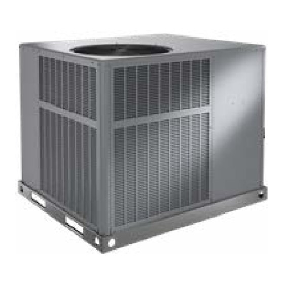
*RP16AC AND *RP16HP SERIES UNITS
RESIDENTIAL PACKAGED UNITS
Air Conditioners and Heat Pumps
507635-05
11/2022
Table of Contents
Unit Dimensions ..........................................................2
Roof Curb Dimensions ................................................4
Adjustable Roof Curb Dimensions...............................6
Installation ...................................................................9
Electrical Wiring .........................................................11
Duct System ..............................................................12
Condensate Drain......................................................12
Sequence of Operation..............................................14
Defrost System ..........................................................15
System Performance .................................................18
Maintenance ..............................................................18
Wiring Diagrams ........................................................21
See Unit Nameplate for Manufacturer
*P507635-05*
CAUTION
Issue 2245
(P) 507635-05
Page 1 of 22
Advertisement
Table of Contents

Related Manuals for Armstrong Air RP16AC Series

Summary of Contents for Armstrong Air RP16AC Series
-
Page 1: Table Of Contents
INSTALLATION AND MAINTENANCE INSTRUCTIONS *RP16AC AND *RP16HP SERIES UNITS RESIDENTIAL PACKAGED UNITS Air Conditioners and Heat Pumps 507635-05 11/2022 THIS MANUAL MUST BE LEFT WITH THE HOMEOWNER FOR FUTURE REFERENCE Table of Contents Unit Dimensions ............2 Roof Curb Dimensions ..........4 Adjustable Roof Curb Dimensions.......6 WARNING Installation ..............9... -
Page 2: Unit Dimensions
Unit Dimensions - Small Base Air Conditioners & Heat Pumps 47.66 2.48 1.98 2.33 2.33 16.77 14.02 RETURN SUPPLY 18.52 11.49 11.49 16.07 TOP VIEW 47.66 POWER ENTRY POWER ENTRY 6.94 3.25 4.56 20.31 21.06 23.19 SIDE VIEWS CONDENSATE 40.89 21.63 DRAIN 3/4 NPT 13.21... - Page 3 Unit Dimensions - Large Base Air Conditioners & Heat Pumps 56.13 2.11 2.39 2.33 2.33 19.49 19.49 RETURN SUPPLY 18.52 11.49 11.49 TOP VIEW 16.07 47.66 POWER ENTRY POWER ENTRY 6.94 3.25 10.06 25.81 26.56 SIDE VIEWS 28.68 44.89 21.63 CONDENSATE DRAIN 3/4 NPT 13.21...
-
Page 4: Roof Curb Dimensions
Roof Curb Dimensions - Small Base Air Conditioners & Heat Pumps 3/4 (19) RETURN Opening for Power Entry OPENING Through Unit Base 5-1/2 x 5-5/8 in. (140 x 31 mm) 16-7/8 44-3/8 (429) (1127) 11-1/2 2-1/8 (287) (54) Insulated Panels 5-3/4 13-7/8 (146) - Page 5 Roof Curb Dimensions - Large Base Air Conditioners & Heat Pumps 3/4 (19) Opening for Power Entry Through Unit Base 5-1/2 x 5-5/8 in. 19-1/2 (140 x 31 mm) 44-3/8 (380) 11-1/2 2-1/8 (1127) (287) (54) RETURN Insulated OPENING Panels 19-1/2 (380) SUPPLY...
-
Page 6: Adjustable Roof Curb Dimensions
Adjustable Roof Curb Dimensions - Small Base Air Conditioners & Heat Pumps (Knock-Down Style) CLIPLOCK CORNER DETAIL Top Edge Wood Nailer Strip CURB PROFILE Bottom Flange Typical Slot Typical Locking Tab NOTE: See Cliplock 1000 installation instructions for complete assembly and installation procedures and requirements. 1-3/4 Opening for Power Line Entry thru base... - Page 7 Adjustable Roof Curb Dimensions - Large Base Air Conditioners & Heat Pumps (Knock-Down Style) CLIPLOCK CORNER DETAIL Top Edge Wood Nailer Strip Bottom Flange CURB PROFILE Typical Slot Typical Locking Tab NOTE: See Cliplock 1000 installation instructions for complete assembly and installation procedures and requirements. 1-3/4 Opening for Power Line Entry thru base...
- Page 8 Adjustable Roof Curb Dimensions - Air Conditioners & Heat Pumps (Welded Style) Front Flange 8 (203) NOTE: Unit Base Rail Minimum Clips (4) Height 4 (102) Built-In Rain Sides and Diverter Back Flange (Not Shown) 6 (152) Built-In Drip Edge Unit Base Rail 3/4 (76) Unit Base Rail...
-
Page 9: Installation
Location The unit is designed to be located outdoors with sufficient WARNING clearance for free entrance to the air inlet and discharge Improper installation, adjustment, alteration, service, air openings. The location must also allow for adequate or maintenance can cause injury or property damage. service access. - Page 10 Compressor • The unit operating conditions (including airflow, cooling operation, ignition, input rate, temperature Units are shipped with compressor mountings factory rise and venting) must be verified according to these adjusted and ready for operation. Do not loosen compressor installation instructions. mounting bolts.
-
Page 11: Electrical Wiring
color-coded to match the connection called out on the wiring schematic. CAUTION NOTE: An optional bottom-entry power kit is available for Before lifting a unit, make sure that the weight is these units. See the kit instructions for proper installation distributed equally on the cables so that it will lift evenly. -
Page 12: Duct System
Use only copper conductors. For downflow duct systems: Remove the duct covers on side of the unit. Keep the If any of the original unit wiring is replaced, the same size screws and the covers as they will be re-installed later. and type wire must be used. - Page 13 to local codes. Use a sealing compound on male pipe Do not operate unit without a drain trap. The condensate threads. drain is on the negative pressure side of the blower; therefore, air being pulled through the condensate line will prevent positive drainage without a proper trap.
-
Page 14: Sequence Of Operation
Heater Kit Accessory (if used) place when the control is communicating with the motor between cycles. This is normal operation. Read through The unit is fully equipped for operation without auxiliary the jumper settings section before adjusting the jumper to heat. -
Page 15: Defrost System
In the cooling mode, the blower control delays blower temperature is below the lock-in temperature (see Second- operation for 5 seconds after the compressor starts. The Stage Lock-In section). The reversing valve is not energized blower continues to operate for 90 seconds after the in the heating mode. - Page 16 Ambient Sensor within the range shown, may be performing as designed. The ambient sensor considers outdoor temperatures However, if a shorted or open circuit is detected, then the below -35°F (-37°C) or above 120°F (48°C) as a fault. If the sensor may be faulty and the sensor harness will needs to be replaced.
- Page 17 • Defrost Mode—The following paragraphs provide a 5-Strike Lockout Feature detailed description of the defrost system operation. The internal control logic of the board counts the pressure switch trips only while the Y1 (Input) line is active. If a Defrost Cycles pressure switch opens and closes four times during a Y1 The control board initiates a defrost cycle based on either (Input), the control logic will reset the pressure switch trip...
-
Page 18: System Performance
Diagnostic LEDs Maintenance The defrost board uses two LEDs for diagnostics. The LEDs flash a specific sequence according to the condition WARNING as shown in Table 4. Before performing maintenance operations on the Defrost Board Diagnostic LEDs system, shut off all electrical power to the unit. Turn off accessory heater power switch if applicable. - Page 19 507635-05 Issue 2245 Page 19 of 22...
- Page 20 Page 20 of 22 Issue 2245 507635-05...
-
Page 21: Wiring Diagrams
Wiring Diagrams Figure 8. AC Wiring Diagram 507635-05 Issue 2245 Page 21 of 22... - Page 22 Figure 9. HP Wiring Diagram Page 22 of 22 Issue 2245 507635-05...
Need help?
Do you have a question about the RP16AC Series and is the answer not in the manual?
Questions and answers