Table of Contents
Advertisement
Quick Links
THIS MANUAL MUST BE LEFT WITH THE
HOMEOWNER FOR FUTURE REFERENCE
Improper installation, adjustment, alteration, service, or
maintenance can cause injury or property damage. Refer
to this manual. For assistance or additional information,
consult a licensed professional (or equivalent), HVAC
installer, service agency, or the gas supplier.
If this unit is to be installed in a mobile or manufactured
home application, the duct system must be sized to
achieve static pressures within the manufacturer's
guidelines. All other installation guidelines must also
be followed. Failure to do so may result in equipment
damage, personal injury, and improper performance of
the unit.
The installation of the unit, wiring, warm air ducts, venting, etc. must conform to the requirements of the National Fire
Protection Association; the National Fuel Gas Code, ANSI Z223.1 (latest edition) and the National Electrical Code, ANSI/
NFPA No. 70 (latest edition) in the United States; the Canadian Installation Codes CAN/CGA-B149.1 & .2 (latest edition)
and the Canadian Electrical Code Part 1, CSA 22.1 (latest edition) in Canada; and any state or provincial laws, local
ordinances, or local gas utility requirements. Local authorities having jurisdiction should be consulted before installation
is made. Such applicable regulations or requirements take precedence over the general instructions in this manual.
507640-05
WARNING
WARNING
Save these instructions for future reference
INSTALLATION AND MAINTENANCE
INSTRUCTIONS
*RP16DF SERIES UNITS
RESIDENTIAL PACKAGED UNITS
Dual Fuel Units
507640-05
11/2022
Table of Contents
Unit Dimensions ..........................................................2
Roof Curb Dimensions ................................................4
Adjustable Roof Curb Dimensions...............................6
Installation ...................................................................9
Venting.......................................................................11
Duct System ..............................................................12
Filters .........................................................................12
Condensate Drain......................................................13
Gas Piping .................................................................13
Electrical Wiring ........................................................14
Gas Heating Start-Up ...............................................15
Sequence of Operation..............................................17
System Performance .................................................21
Control System Diagnostics ......................................22
Maintenance ..............................................................23
Wiring Diagrams ........................................................25
Do not store combustible materials, including gasoline
and other flammable vapors and liquids, near the unit,
vent pipe, or warm air ducts. Such actions could cause
property damage, personal injury, or death.
See unit nameplate for Manufacturer
*P507640-05*
CAUTION
Issue 2245
WARNING
(P) 507640-05
Page 1 of 25
Advertisement
Table of Contents

Related Manuals for Armstrong Air RP16DF Series

Summary of Contents for Armstrong Air RP16DF Series
-
Page 1: Table Of Contents
INSTALLATION AND MAINTENANCE INSTRUCTIONS *RP16DF SERIES UNITS RESIDENTIAL PACKAGED UNITS Dual Fuel Units 507640-05 11/2022 Table of Contents Unit Dimensions ............2 Roof Curb Dimensions ..........4 THIS MANUAL MUST BE LEFT WITH THE Adjustable Roof Curb Dimensions.......6 HOMEOWNER FOR FUTURE REFERENCE Installation ..............9... -
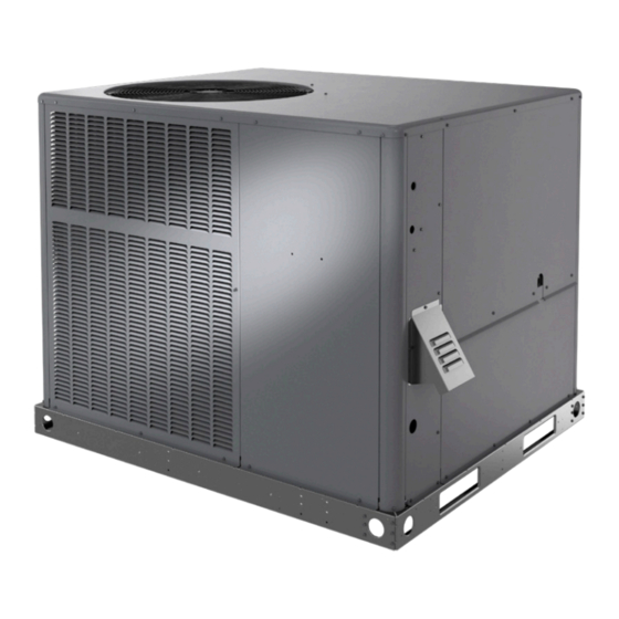
Page 2: Unit Dimensions
Unit Dimensions - Small Base Dual Fuel 47.66 2.48 1.98 2.33 2.33 16.77 14.02 RETURN SUPPLY 18.52 11.49 11.49 16.07 TOP VIEW 47.66 POWER ENTRY GAS ENTRY 6.94 3.25 4.56 20.31 21.06 23.19 SIDE VIEWS CONDENSATE DRAIN 3/4 NPT 5.75 3.55 40.89 21.63... - Page 3 Unit Dimensions - Large Base Dual Fuel 56.13 2.11 2.39 2.33 2.33 19.49 19.49 RETURN SUPPLY 18.52 11.49 11.49 TOP VIEW 16.07 47.66 POWER ENTRY GAS ENTRY 6.94 3.25 10.06 25.81 26.56 28.68 SIDE VIEWS CONDENSATE DRAIN 3/4 NPT 5.75 3.55 44.89 21.63...
-
Page 4: Roof Curb Dimensions
Roof Curb Dimensions - Small Base Dual Fuel 3/4 (19) RETURN Opening for Power Entry OPENING Through Unit Base 5-1/2 x 5-5/8 in. (140 x 31 mm) 16-7/8 44-3/8 (429) (1127) 11-1/2 2-1/8 (287) (54) Insulated Panels 5-3/4 13-7/8 (146) (352) SUPPLY 5-1/2... - Page 5 Roof Curb Dimensions - Large Base Dual Fuel 3/4 (19) Opening for Power Entry Through Unit Base 5-1/2 x 5-5/8 in. 19-1/2 (140 x 31 mm) 44-3/8 (380) 11-1/2 2-1/8 (1127) (287) (54) RETURN Insulated OPENING Panels 19-1/2 (380) SUPPLY OPENING 11-1/2 (287)
-
Page 6: Adjustable Roof Curb Dimensions
Adjustable Roof Curb Dimensions - Small Base Dual Fuel (Knock-Down Style) CLIPLOCK CORNER DETAIL Top Edge Wood Nailer Strip CURB PROFILE Bottom Flange Typical Slot Typical Locking Tab NOTE: See Cliplock 1000 installation instructions for complete assembly and installation procedures and requirements. 1-3/4 Opening for Power Line Entry thru base... - Page 7 Adjustable Roof Curb Dimensions - Large Base Dual Fuel (Knock-Down Style) CLIPLOCK CORNER DETAIL Top Edge Wood Nailer Strip Bottom Flange CURB PROFILE Typical Slot Typical Locking Tab NOTE: See Cliplock 1000 installation instructions for complete assembly and installation procedures and requirements. 1-3/4 Opening for Power Line Entry thru base...
- Page 8 Adjustable Roof Curb Dimensions (Welded Style) Front Flange 8 (203) NOTE: Unit Base Rail Minimum Clips (4) Height 4 (102) Built-In Rain Sides and Diverter Back Flange (Not Shown) 6 (152) Built-In Drip Edge Unit Base Rail 3/4 (76) Unit Base Rail Clips (4) (152) 42-7/8...
-
Page 9: Installation
Installation Condenser coils must have an unlimited supply of air. For ground level installation, use a level prefabricated These instructions must be saved for future reference. pad or use a level concrete slab. Do not tie the slab to the building foundation. The heat pump unit These units are single package heat pumps with gas heat, designed for outdoor installation on a rooftop or slab. - Page 10 • Air filters must be replaced and pre-filters must be Clearance to Clearance for removed upon construction completion. Combustibles Service Access • The input rate and temperature rise must be set per Front of unit 0 in. 24 in. the unit rating plate. Back of unit 0 in.
-
Page 11: Venting
All panels must be in place for rigging. 4 feet horizontally from, or 1 foot above any door, window, or gravity air inlet into the building. The vent system shall Place field-provided spreaders in place. Spreaders terminate at least 3 feet above any forced air inlet located must be of adequate strength and length (must exceed within 10 feet. -
Page 12: Duct System
Removal of Unit from Common Venting System Duct System When an existing furnace is removed from a common The duct system should be designed and sized according venting system serving other appliances, the venting to the methods in the Air Conditioning Contractors of system is likely to be too large to properly vent the America (ACCA) manual that is most appropriate to the remaining attached appliances. -
Page 13: Condensate Drain
NOTE: Minimum Pitch: 1 in (25) Per 10” The filter rack must be installed prior to installation of (3048 mm) of Unit the unit in applications where access to the rear panel Line is limited. Open Vent Unit Model Filter 1 Filter 2 24, 36 14 x 20 x 1... -
Page 14: Electrical Wiring
• The gas supply should be a separate line and installed When converting a low NOx unit (designated by an L in in accordance with all safety codes listed on Page 1. some model numbers) to propane, the NOx inserts must After the gas connections have been completed, open be removed. -
Page 15: Gas Heating Start-Up
must be sized to carry minimum circuit ampacity marked on the unit. Use copper conductors only. Each unit must be THERMOSTAT OUTDOOR UNIT wired with a separate branch circuit and be properly fused. NOTE: An optional bottom-entry power kit is available for Blue these units. - Page 16 Set the room thermostat to the desired temperature. The manifold pressure can be measured by shutting off (If the thermostat “set” temperature is above room the gas, removing the pipe plug in the downstream side temperature after the pre-purge time expires, main of the gas valve, and connecting a water manometer or burners will light.) gauge.
-
Page 17: Sequence Of Operation
Slide the gas valve switch to the “ON” position and Remove the screws that secure the burner box initiate a call for heat. If manifold pressure must be assembly to the vest panel and remove the assembly from the unit. adjusted, remove cap from pressure regulator and turn adjustment screw clockwise to increase pressure Remove the screws that fasten the burner rack... - Page 18 CONTINUOUS FAN The CFM LED located on the blower control flashes one time per 100 cfm to indicate selected blower speed. For When the thermostat is set for “Continuous Fan” operation example, if the unit is operating at 1200 CFM, the CFM and there is no demand for heating or cooling, the blower LED will flash 12 times.
- Page 19 Defrost System Temperature Red LED Pins / Wire Sensor Demand Defrost System Range °F (°C) (DS1) Color The demand defrost system measures differential Outdoor -35 (-37) to 280,000 to 3 & 4 temperatures to detect when the system is performing (ambient) 120 (48) 3750...
- Page 20 Actuation performance testing. The feature is deactivated by When the reversing valve is de-energized, the Y1 circuit is removing the jumper located on the compressor delay pins energized, and the coil temperature is below 35°F (2°C), on the control board mounted inside the unit control box. This feature is optional for the homeowner, but may impact the board logs the compressor run time.
-
Page 21: System Performance
When the pre-purge period has expired, the ignition Defrost Board Diagnostic LEDs control energizes the main gas valve and spark Green LED Red LED electrode for a period of 10 seconds. Condition (DS2) (DS1) If the flame sensor does not sense that a flame has No Power to Control been established in the 10-second interval, then the ignition control will de-energize the gas valve, and... -
Page 22: Control System Diagnostics
Control System Diagnostics LED Status Flashing Rate Fault Description One flash per Normal operation: Slow Flash second No call for heat Two flashes per Normal operation: Fast Flash second Call for heat Two flashes in System lockout: 2 Flash 1 second with Failed to detect or 1-second pause sustain flame... -
Page 23: Maintenance
Heat Exchanger Maintenance With proper combustion adjustment, the heat exchanger Periodic inspection and maintenance normally consists of of a gas-fired furnace will seldom need cleaning. Sooting changing or cleaning the filters and cleaning the evaporator of a gas appliance is highly irregular and once cleaned, coil. - Page 24 Page 24 of 25 Issue 2245 507640-05...
-
Page 25: Wiring Diagrams
Wiring Diagrams Figure 10. DF Wiring Diagram 507640-05 Issue 2245 Page 25 of 25...
Need help?
Do you have a question about the RP16DF Series and is the answer not in the manual?
Questions and answers