Advertisement
Quick Links
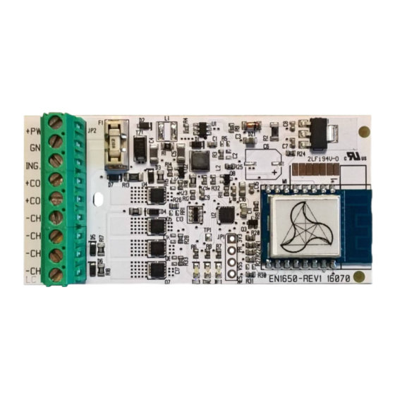
Collegamenti e configurazione uscite
Esempio scheda
Per connettere ulteriori schede a LED aggiungere amplificatore es.:
In order to connect additional LED boards add an amplifier e.g.:
1200EN1010-A-V24
1200EN0735–RGBFC
Max 10+10+10+10+10+10+4 pz / pcs
connessi in parallelo / connected in parallel
1200EN1251-XXX-0-L314V24
Max 19 pz / 19 pcs max
1300LL060N-RGBW1-05024
Max 5+3,3m connessi in parallelo / connected in parallel
Esempio scheda
Per connettere ulteriori schede a LED aggiungere amplificatore es.:
In order to connect additional LED boards add an amplifier e.g.:
1200EN1010-A-V24
1200EN0735–RGBFC
Max 10+10+10+10+10+10+4 pz / pcs
connessi in parallelo / connected in parallel
Configurazione
Prima di alimentare la scheda
premere e mantenere premuto il pulsante
successivamente fornire alimentazione alla scheda
si accenderà un'uscita ad indicare l'impostazione settata
Canale acceso per segnalazione
Switched ON channel for signal
Tipo scheda connessa in uscita
LED board type connected in output
Nel caso al primo tentativo
non venisse visualizzato il settaggio desiderato
togliere l'alimentazione e ripetere i passaggi sopra
www.entityel.com
info@entityel.it
MANUALE / USER MANUAL
EN1650 DomoVoice
RGBW
collegata in uscita
RGB
collegata in uscita
Prior to Switch ON the board
press and keep pressed the button
after, supply the board
an output will be switch ON in order to signal setted setting
CH1 (ROSSO)
CH2 (RED)
RGBW
1200EN0735–RGBFC
Max 10+10+10+10+4 pz / pcs
connessi in parallelo / connected in parallel
If the first attempt, will not display the desired setting
take off the power supply and repeat the paragraph
reported above
1200EN1251-XXX-0-L314V24
Max 13 pz / 13 pcs max
1
Connection and outputs configuration
RGBW
board connected in output example
PULSANTE ESTERNO / EXTERNAL BUTTON
Collegarlo tra ING.P (BTN) e uno dei 2 COM
Connect between ING.P (BTN) and 1 of 2 COMs
I
CH1
RGB
board connected in output example
PULSANTE ESTERNO / EXTERNAL BUTTON
Collegarlo tra ING.P (BTN) e uno dei 2 COM
Connect between ING.P (BTN) and 1 of 2 COMs
I
+I
CH1
CH2 (VERDE)
CH2 (GREEN)
RGB
Controller
+I
+I
+I
=5A MAX
CH2
CH3
CH4
+I
=5A MAX
CH2
CH3
Set up
Alimentatore
Power Supply
V1.4 M.C.
13/10/2020
24 Vdc
Advertisement

Related Manuals for Entity DomoVoice EN1650

Summary of Contents for Entity DomoVoice EN1650
- Page 1 MANUALE / USER MANUAL Controller EN1650 DomoVoice V1.4 M.C. 13/10/2020 Collegamenti e configurazione uscite Connection and outputs configuration Esempio scheda RGBW collegata in uscita RGBW board connected in output example PULSANTE ESTERNO / EXTERNAL BUTTON Per connettere ulteriori schede a LED aggiungere amplificatore es.: Collegarlo tra ING.P (BTN) e uno dei 2 COM In order to connect additional LED boards add an amplifier e.g.: Connect between ING.P (BTN) and 1 of 2 COMs...
- Page 2 MANUALE / USER MANUAL Controller EN1650 DomoVoice V1.4 M.C. 13/10/2020 Esempio scheda Bianco dinamico collegata in uscita Dynamic white board connected in output example Alimentatore Power Supply 24 Vdc Per connettere ulteriori schede a LED aggiungere amplificatore es.: In order to connect additional LED boards add an amplifier e.g.: 1200EN1010-A-V24 1200EN1430-xCW-H-L314V24 Max 5 + 5 + 5 + 1,6m connessi in parallelo...
- Page 3 MANUALE / USER MANUAL Controller EN1650 DomoVoice V1.4 M.C. 13/10/2020 Configurazione App App configuration Installare l'applicazione “Tuya smart” Install the “Tuya smart” App Link Google Play store (Android) Link Apple App Store (iOS) * Se si è già in possesso di un account, è possibile omettere i punti da 1 a 6 In case of an existing account, skip the steps from 1 to 6 Aprire l'applicazione Open the “Tuya smart”...
- Page 4 MANUALE / USER MANUAL Controller EN1650 DomoVoice V1.4 M.C. 13/10/2020 Inserire il codice ricevuto Enter the verification code Impostare una password Set a password Aggiungere una “casa” dove sarà installato il dispositivo Add the “home” where the device will be installed typing “Add premendo “aggiungi casa”...
-
Page 5: Installazione
MANUALE / USER MANUAL Controller EN1650 DomoVoice V1.4 M.C. 13/10/2020 Inserire le seguenti informazioni: Add the following informations: - nome della casa - name of the house - posizione geografica (opzionale) - geographic location (not mandatory) - selezionare le stanze predefinite select the predefined rooms by pressing the premendo il cerchio arancione allineato orange circle aligned to the room name... - Page 6 MANUALE / USER MANUAL Controller EN1650 DomoVoice V1.4 M.C. 13/10/2020 Selezionare “Illuminazione” nella colonna di sinistra Select “Lighting” into the column on the right Selezionare “Dispositivi di illuminazione” con il simbolo Select “Lighting” with bulb symbol della lampadina Selezionare “Confermata Nella Lampada Istantanea” Select “Confirm light blinks rapidly”...
- Page 7 MANUALE / USER MANUAL Controller EN1650 DomoVoice V1.4 M.C. 13/10/2020 A questo punto le schede LED smetteranno di At this point, the LED modules will stop blinking and lampeggiare e verrà richiesto il nome da it will be required to set the name of your assegnare al DomoVoice, premendo DomoVoice, by pressing the pencil icon and the sull'icona della matita e il nome della stanza...
- Page 8 MANUALE / USER MANUAL Controller EN1650 DomoVoice V1.4 M.C. 13/10/2020 Associazione con assistente vocale Pairing with the vocal assistant Se non installato, fare riferimento ai seguenti link If not installed, refer to the below links Google Home Amazon Alexa Clicca qui / Click here Google Home Clicca qui / Click here Amazon Echo Google Home...
- Page 9 MANUALE / USER MANUAL Controller EN1650 DomoVoice V1.4 M.C. 13/10/2020 Eseguire l'accesso con i dati inseriti nei Login with credentials (set before - points 3 passaggi 3 e 5 e premere “Link Now”. and 5) and press “Link Now”. Successivamente premere “Authorize” Press “Authorize”.
- Page 10 MANUALE / USER MANUAL Controller EN1650 DomoVoice V1.4 M.C. 13/10/2020 Una volta assegnata la stanza, When the room is assigned to the device, il nome della stanza comparirà sotto il the room name will appear below lamp's nome della lampada. name.
-
Page 11: Amazon Alexa
MANUALE / USER MANUAL Controller EN1650 DomoVoice V1.4 M.C. 13/10/2020 Amazon Alexa Con l'assistente Amazon Alexa è possibile configurare il dispositivo in 2 With Amazon Alexa assistant is possible to setup the device in 2 ways: modi: - through a web browser (17AB – 26AB steps pages 10 - 12 ) - attraverso un browser web (passaggi 17AB –... - Page 12 MANUALE / USER MANUAL Controller EN1650 DomoVoice V1.4 M.C. 13/10/2020 21AB Eseguire l'acceso con i dati inseriti nei passaggi 3 e 5. Login with credentials (set before points 3 and 5). Premere “Link Now”. Press “Link Now” Successivamente premere “Authorize” Press “Authorize”...
- Page 13 MANUALE / USER MANUAL Controller EN1650 DomoVoice V1.4 M.C. 13/10/2020 24AB E' possibile inserire le lampade in gruppi in modo da gestire più lampade It is possible to create groups of lamps, in order to control more lamps contemporaneamente. simultaneously. Premere “Casa Intelligente”...
- Page 14 MANUALE / USER MANUAL Controller EN1650 DomoVoice V1.4 M.C. 13/10/2020 Aprire l'applicazione “Amazon Alexa” Open the “Amazon Alexa” App 17AA 18AA Premere l'icona con le 3 linee Tap on the icon with 3 horizontal lines on top orizzontali in alto a sinistra e left and select “Skills &...
- Page 15 MANUALE / USER MANUAL Controller EN1650 DomoVoice V1.4 M.C. 13/10/2020 21AA Eseguire l'acceso con i dati inseriti nei passaggi 3 e 5. Login with credentials (set before points 3 and 5). Premere “Link ora”. Press “Link Now” Successivamente premere “Autorizzare” Press “Authorize”...
- Page 16 MANUALE / USER MANUAL Controller EN1650 DomoVoice V1.4 M.C. 13/10/2020 E' possibile inserire le lampade in It is possible to create groups of lamps, in 24AA gruppi in modo da gestire più order to control more lamps simultaneously. lampade contemporaneamente. Press on the house shape icon on the right Premere sull'icona a forma di casa in bottom...
- Page 17 MANUALE / USER MANUAL Controller EN1650 DomoVoice V1.4 M.C. 13/10/2020 Comandi Vocali Vocal commands Google Home "Ok Google" può essere sostituito da "Hey Google" "Ok Google" can be replaced by "Hey Google" [dispositivo] può essere Per comandare [device] can be To control [Nome lampada] [Lamp name]...
- Page 18 stress.
Need help?
Do you have a question about the DomoVoice EN1650 and is the answer not in the manual?
Questions and answers