Table of Contents
Advertisement
Advertisement
Table of Contents

Related Manuals for WaterSoft Provectr Plus AF10AC-3


Summary of Contents for WaterSoft Provectr Plus AF10AC-3
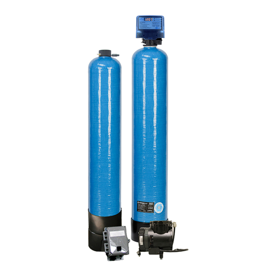
- Page 1 Provectr Plus Installation / Operation Manual...
-
Page 2: Table Of Contents
Filter Specifications............Page 3 Installation................Page 4 Programming the Control Valve........Page 8 Master Programming............Page 10 Utilizing Bluetooth............. Page 11 Powerhead Assembly............Page 14 Valve Body Assembly............Page 15 Bypass Assembly............... Page 17 Service Instructions............Page 18 Troubleshooting..............Page 19 Error Codes................. -
Page 3: Filter Specifications
Provectr Plus Specifications General Specifications AF10AC-3 AF12AC-3 AF13AC-3 AF14AC-3 SmartBlend ™ Filter Media Type Filter Media Capacity (cu ft) Provectr ® Tank Size 10 x 54 10 x 54 10 x 54 16 x 40 Mineral Tank Size 10 x 54 12 x 52 13 x 54 13 x 65... -
Page 4: Installation
Installation PROVECTR PLUS PROVECTR FILTER -Installation Requirements- A/P Tank • A level floor position between the well pump and pressure tank. (See Typical Installation Diagram.) • DO NOT install in an area of direct sunlight or where freezing temperatures may occur! Filter Tank •... - Page 5 Installation -PROVECTR Plus Location / Other Requirements- • Locate the filter near a 120 volt / 60 Hz grounded electrical outlet. • Check for distance and proper drain installation (e.g. floor drain, washing machine standpipe). • Determine type and size of piping required for PROVECTR connection (e.g. galvanized, PVC plastic). Note: If household plumbing is galvanized and you intend to make an installation with copper (or vice ver sa), obtain di-electric unions to prevent dissimilar metal corrosion.
- Page 6 Installation - Water Supply Connection and Bypass Valve - To allow for servicing, swimming pool filling or lawn sprinkling, a manual Bypass Valve has been installed at the factory. The Bypass allows raw water to be manually routed around the filter. 1.
- Page 7 Installation - Air Compressor / Relay Box – • Locate the air compressor in close proximity to the AP tank assembly. • Connect the supplied tubing to the compressor and the other end to the AP tank manifold insert. • Insert the compressor’s electrical plug into the relay box. •...
-
Page 8: Programming The Control Valve
Programming the Control Valve Warning: Close handle on bypass prior to selecting the backwash position. After backwash position has been established, slightly open valve on bypass to evacuate air from the media tank. Fully open bypass valve when all air is depleted. This procedure will prevent media form being uplifted into control valve. - Page 9 Programming the Control Valve 5. To Exit Main Menu, press the Menu/Enter button. Note: If no buttons are pressed for 60 seconds, the Main Menu will be exited automatically. Normal Operation 1. Home Display a. Alternates between the display of Time of Day and Number of Days until the Next Backwash. (Metered Softeners will alternate between time of days and gallons remaining until next regeneration) - Days Remaining until the Next Backwash will count down from the entered value until it...
-
Page 10: Master Programming
Master Programming Mode Filters Default (Min) Step 1 Backwash Step 2 Rest Step 3 Rapid Rinse Step 4 Not Used Master Programming Mode To enter Master Programming Mode, press and hold both buttons for 5 seconds. Note: All Master Programming functions have been preset at the factory. Unless a change is desired, it is NOT necessary to enter Master Programming Mode. -
Page 11: Utilizing Bluetooth
Utilizing Bluetooth Control For simplified set up and control, please install the Legacy View on a compatible Bluetooth 4.0+ enabled smart phone or tablet. 1. Download and install the Legacy View app from the Google Play Store, Apple App Store 2. - Page 12 Set Up Utilizing Bluetooth App Change Time of Day (Press “SET” to set time automatically based on device). For Filters: Set Backwash Frequency This sets the amount of day between backwash cycles Set Regeneration Time Example: For 2a.m., just type 2, choose a.m., and press ‘OK’ Note: If you have a filter and a softener the valves should be set to regenerate at different times.
- Page 13 Set Up Utilizing Bluetooth App Status and History From the Status and History, all items in ORANGE can be reset. Pressing this icon will show a list of the data that is in the graph. Touch any graph to enlarge and see details.
-
Page 14: Powerhead Assembly
Control Valve Powerhead Assembly LETTERS IN DIAGRAM REPRESENT WIRING CONNECTIONS DESCRIPTION PART NO. Provectr™ Power Head Assy. 20942C100 Provectr™ Circuit Boad Assy. 20942C102 Encoder 20001X124 Front Plate 20001X004 Encoder Wheel 20001X007 Main Gear 21001X120 Power Supply 20001X125 Back Plate 20001X005 Lower Front Base For Cover 20111X002 Motor... -
Page 15: Valve Body Assembly
Valve Body Drive Assy. - Page 16 Valve Body Drive Assy. DESCRIPTION PART NO. Final Rinse Piston Assembly 20009X231 10-24 X 3/4” Screw SST 20001X001 Seal and Spacer Kit Incl (5) #3 & (4) #4 20561X253 End Spacer 20001X234 Flow Control Button 5.0 GPM 20251X272 Flow Control Button 7.0 GPM 20251X273 DLFC Housing 20017X251...
-
Page 17: Bypass Assembly
Bypass Assembly DESCRIPTION PART NO. D15 Bypass (included with all units) 20017X283 1” NPT Elbow Set (included with all units) 20017X284 1” Female Straight Slip Set (optional) 20017X288 1” NPT Straight Set (optional) 20017X289 3/4” NPT Straight Set (optional) 20017X307 1”... -
Page 18: Service Instructions
Service Instructions / Instructional Videos available at www.watersoftinc.com General Preliminary Instructions PERFORM BEFORE ALL SERVICING OPERATIONS 1. Turn off water supply to conditioner. -If the conditioner installation has a “three valve” bypass system, first open the valve in the by pass line, then close the valves at the conditioner inlet and outlet. -
Page 19: Troubleshooting
Troubleshooting Guide and Error Codes To Replace Meter 1. Follow steps A1 - A3 2. Unplug meter cable from front of circuit board. 3. Unscrew meter assembly nut from valve body. 4. Remove meter from valve body and clean or replace as necessary. 5. -
Page 20: Error Codes
Error Codes Error 2 - Valve is searching for homing slot. Allow valve to continue running. If the homing slot is found, the valve will return to the home display, oth- erwise, another error code will appear. Error 3 - No encoder slots are being seen. This occurs when the motor is running, but the encoder is not seeing any of the slots in the encoder wheel. -
Page 21: Warranty Information
PRODUCT BE LIABLE FOR MORE THAN, AND PURCHASER- USER’S REMEDIES SHALL NOT EXCEED, THE PRICE PAID FOR WATERSOFT will at its option either make repairs to correct any THE PRODUCT. IN NO CASE SHALL WATERSOFT OR SELLER defect in material or workmanship or supply and ship either new or BE LIABLE FOR ANY SPECIAL, INCIDENTAL, CONTINGENT OR used replacement parts or products. - Page 24 710 Orange Street, Ashland, OH 44805 PH 419.289.1500 FAX 419.289.1515 www.watersoftinc.com 0922TV...
Need help?
Do you have a question about the Provectr Plus AF10AC-3 and is the answer not in the manual?
Questions and answers