Table of Contents
Advertisement
Available languages
Available languages
Quick Links
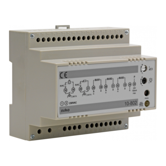
10-801 /10-802
Lees de volledige handleiding vóór installatie en ingebruikname.
1. Beschrijving
De voedingsmodules kunnen een audiodeurcommunicatiesysteem voeden en programmeren.
Bij een groot systeem of een systeem met een buitenpost met een LCD-scherm en/of video
is een bijkomende gelijkspanningsvoeding vereist.
Beide voedingsmodules zijn ontworpen voor montage in een DIN-rail kast. De maximale
configuratie van een audiosysteem wordt in tabel 1 weergegeven.
De voedingsmodules werken op de standaardnetspanning (230V~, 50Hz) en leveren gelijkspanning
voor het systeem. Naast het aansluiten van de binnen- en buitenposten op deze voedingsmodules
is het ook mogelijk een deuropener en/of een lichtpunt aan te sturen via de voedingsmodule. U
kan de tijd voor de aansturing van de deuropener en de verlichting instellen.
2. Montage
De voedingsmodules zijn geschikt voor montage in een DIN-rail kast. U sluit de voedingsmodules
aan door de netvoeding op klemmen 1 en 3 van de voedingsmodule aan te sluiten. Voor de
aansluiting van de binnen- en buitenpost(en) op de voedingsmodule, fig.1.
Volgende kabels kunnen voor de aansluiting van de binnen- en buitenpost(en) gebruikt
worden: JYSTY(-F2) 3 x 2 x 0,8mm of TPVF 3 x 2 x 0,6mm (beperkt de omvang van het
systeem, zie tabel 2.).
Niet alle paren worden in een systeem zonder video gebruikt. Toch raden wij aan om steeds
3 paren te voorzien om latere uitbreiding naar een videosysteem mogelijk te maken.
voeDing 20 (10-801)
Als u slechts over één of twee buitenposten beschikt, kan u kiezen tussen een 2-draads
of 3-draads bedrading. Bij een 2-draads audiosysteem (fig.1) hoeft u enkel nog de P-klem
intern (in de buitenpost) met de a-klem te verbinden, zodat de naamplaat verlicht wordt. Bij
een 3-draads aansluiting (fig.1) wordt de P-ader via de voeding met de buitenpost vebonden.
Bijgevolg hoeven de klemmen P en a NIET meer intern doorverbonden te worden! Voor de
binnenposten volstaat een 2-draads bedrading.
Een deuropener (optioneel) dient op klemmen 16 en 17 van de voedingsmodule (VOEDING
20) aangesloten te worden.
voeDing 100 (10-802)
Deze voeding wordt enkel gebruikt voor grote systemen. Een 3-draads bedrading naar de
buitenpost is vereist. Naar de binnenposten kan nog steeds met 2 aders gewerkt worden (fig.
2). De voeding van de binnen- en buitenposten wordt over 3 bussen verdeeld.
De deuropener (optioneel) sluit u aan op klemmen 20 en 21 van de voedingsmodule
(VOEDING 100).
NL
1
Advertisement
Table of Contents

Subscribe to Our Youtube Channel
Related Manuals for Niko 10-801


Summary of Contents for Niko 10-801
- Page 1 Niet alle paren worden in een systeem zonder video gebruikt. Toch raden wij aan om steeds 3 paren te voorzien om latere uitbreiding naar een videosysteem mogelijk te maken. voeDing 20 (10-801) Als u slechts over één of twee buitenposten beschikt, kan u kiezen tussen een 2-draads of 3-draads bedrading.
- Page 2 10-801 /10-802 Max. # voeDing buitenposten* 10-801 10-802 10-802 & > 5 10-805-01 Tabel 1: max. aantal configuraties met de audiovoedingen Let oP: De maximum af te leggen afstanden hangen af van de gebruikte kabel en van het aantal buitenposten op de lijn (zie tabel 2).
- Page 3 10-801 /10-802 Max.20ex. 05-540 A B E P 12V 1A max 10-501 05-540 A B E P 12V 1A max 10-511 10-173 Relais 10-835 1 4 1 5 1 6 1 7 1 8 1 9 2 0 2 1 2 2 2 3 2 4 2 5...
-
Page 4: Werking En Gebruik
10-801 /10-802 3. Werking en geBruik Als de installatie correct is uitgevoerd en op het net wordt aangesloten, zal de LED op de voedingsmodule oplichten. Aan de buitenpost licht de LED op, en verlicht de vandaalbe- stendige naamplaat. U kan nu met de bezoeker communiceren door de hoorn van de binnenpost af te haken. De verbinding wordt verbroken door gewoon in te haken of automatisch na 60s. - Page 5 10-801 /10-802 Lichtschakeling koppelen Op het potentiaalvrij contact (24V en 1A) van de voedingsmodules kan een lichtkring aangesloten worden. Sluit de lichtschakeling aan op klemmen 14 en 18 (15 en 16 doorverbinden) van VOEDING 20, zie fig.3 en op klemmen 18 en 19 van VOEDING 100, zie fig.4. Om de kring te voeden is een extra transfo vereist (afhankelijk van de gekoppelde last/weerstand).
- Page 6 10-801 /10-802 Om deze mode op de voeding te activeren of te deactiveren, gaat u als volgt te werk: 14 15 16 17 18 19 20 21 22 23 24 25 14 15 16 17 18 19 20 21 22 23 24 25...
- Page 7 10-801 /10-802 stap 2: een drukknop programmeren (enkel indien het een nieuwe programmering betreft. Overschrijven is onmogelijk. Zie ‘resetten van een drukknop’). De hoorn afhaken Op de beldrukknop drukken. De hoorn terug inhaken U hoort het belsignaal aan de binnen- en de buitenpost.
- Page 8 10-801 /10-802 stap 4: de programmeerstatus beëindigen. 18 19 20 21 22 23 24 25 26 27 28 29 30 31 32 33 34 35 18 19 20 21 22 23 24 25 26 27 28 29 30 31 32 33 34 35...
-
Page 9: Technische Gegevens
- Deze handleiding dient aan de gebruiker te worden overhandigd. Zij moet bij het dossier van de elektrische installatie worden gevoegd en dient te worden overgedragen aan eventuele nieuwe eigenaars. Bijkomende exemplaren zijn verkrijgbaar via de Niko-website of -supportdienst. - Bij de installatie dient rekening gehouden te worden met (lijst is niet limitatief): - de geldende wetten, normen en reglementen;... - Page 10 10-801 /10-802 - Bij twijfel kan u de supportdienst van Niko raadplegen of contact opnemen met een erkend controleorganisme. Support België: Support Nederland: tel. + 32 3 778 90 80 tel. + 31 183 64 06 60 website: http://www.niko.be website: http://www.niko.nl e-mail: support@niko.be...
-
Page 11: Montage
Toutes les paires ne sont pas utilisées dans un système sans vidéo, mais nous conseillons de prévoir quand même toujours 3 paires pour permettre l’extension vers un système vidéo! aLiMentation 20 (10-801) Si vous disposez seulement d’un ou de deux postes extérieurs, vous avez le choix entre un raccordement à... - Page 12 10-801 /10-802 Max. # aLiMenta- postes tion extérieurs* 10-801 10-802 10-802 & > 5 10-805-01 Tableau 1: nombres max. de configurations avec les alimentations audio attention: Les distances max. pouvant être parcourues dépendent du câble utilisé et du nombre de postes extérieurs sur la ligne (voir tableau 2).
- Page 13 10-801 /10-802 Max.20ex. 05-540 A B E P 12V 1A max 10-501 05-540 A B E P 12V 1A max 10-511 10-173 Relais 10-835 1 4 1 5 1 6 1 7 1 8 1 9 2 0 2 1 2 2 2 3 2 4 2 5 2 fils vers poste intérieur...
-
Page 14: Fonctionnement Et Utilisation
10-801 /10-802 3. FonctionneMent et utiLisation Si l’installation a été réalisée correctement et l’installation est connectée au réseau, la LED sur le module d’alimentation s’illuminera. Sur le poste extérieur la LED s’illumine, de façon à ce que le porte-étiquette résistant au vandalisme soit éclairé. - Page 15 10-801 /10-802 raccordement d’une commande d’éclairage Sur le contact libre de potentiel (24V et 1A) des modules d’alimentation, il est possible de raccorder un circuit d’éclairage. Raccordez la commande d’éclairage sur les bornes 14 et 18 d’ALIMENTATION 20 (raccordez les bornes 15 et 16), voir fig.3 et sur les bornes 18 et 19 d’ALIMENTATION 100, voir fig.4.
- Page 16 10-801 /10-802 Pour activer ou désactiver ce mode sur l’alimentation, procédez comme suit: 14 15 16 17 18 19 20 21 22 23 24 25 14 15 16 17 18 19 20 21 22 23 24 25 14 15 16 17 18 19 20 21 22 23 24 25 activer: ➧...
- Page 17 10-801 /10-802 etape 2: programmation du bouton-poussoir (Il s’agit uniquement d’une nouvelle programmation, l’écrasement ne fonctionne pas! Voir ‘Remise à zéro d’un bouton-poussoir’). Décrocher le combiné Appuyer sur le bouton de sonnerie. Raccrocher le combiné Le signal d’appel est entendu sur le poste intérieur et extérieur! remise à...
- Page 18 10-801 /10-802 etape 4: arrêt du mode programmation. 18 19 20 21 22 23 24 25 26 27 28 29 30 31 32 33 34 35 18 19 20 21 22 23 24 25 26 27 28 29 30 31 32 33 34 35...
-
Page 19: Caracteristiques Techniques
- ce mode d’emploi qui doit être lu dans le cadre de toute installation spécifique; - les règles de l’art. - En cas de doute, vous pouvez appeler le service ‘support Niko’ ou vous adresser à un organisme de contrôle reconnu. -
Page 20: Conditions De Garantie
à un remplacement gratuit selon l’avis de Niko. - Niko ne peut être tenu pour responsable pour un défaut ou des dégâts suite à une installation fautive, à une utilisation contraire ou inadaptée ou à une transformation du produit. -
Page 21: Installation
Not all pairs are used in a system without video. Yet we do recommend to always provide 3 pairs in order to allow future extension to a video system. PoWer suPPLY 20 (10-801) If you only have 1 or 2 external units, you can choose between 2- or 3-wire wiring. In a 2-wire audio system (fig.1), you only need to jumper the P terminal (in the external unit) and the... - Page 22 10-801 /10-802 PoWer max. # external suPPLY units* 10-801 10-802 10-802 & > 5 10-805-01 table 1: max. number of internal and external units depending on the power supply used note: the max. distances to be covered depend on the cable used and the number of external units on the line (see table 2).
- Page 23 10-801 /10-802 Max.20ex. 05-540 A B E P 12V 1A max 10-501 05-540 A B E P 12V 1A max 10-511 10-173 Relais 10-835 1 4 1 5 1 6 1 7 1 8 1 9 2 0 2 1 2 2 2 3 2 4 2 5...
-
Page 24: Possible Settings
10-801 /10-802 3. oPeraton anD use If the installation has been carried out correctly and the system is connected to the mains, the LED on the power supply module will lighten up. The LED on the external unit also lightens up, thereby illuminating the antivandal nameplate. - Page 25 10-801 /10-802 connecting a light circuit A light circuit can be connected to the potential free contact (24V and 1A) of the power supply modules. Connect the light circuit to terminals 14 and 18 (jumpering 15 and 16) of POWER SUPPLY 20, see fig.3 and to terminals 18 and 19 of POWER SUPPLY 100, see fig.4.
- Page 26 10-801 /10-802 In order to activate or deactivate this mode on the power supply, proceed as follows: 14 15 16 17 18 19 20 21 22 23 24 25 14 15 16 17 18 19 20 21 22 23 24 25...
- Page 27 10-801 /10-802 step 2: programming a push-button (With a new programming. Overwriting is not possible. See ‘Resetting a push-button’). Pick up the receiver Press the bell push-button. Put the receiver down You hear the ringing signal both on the internal and external unit.
- Page 28 10-801 /10-802 step 4: ending programming status 18 19 20 21 22 23 24 25 26 27 28 29 30 31 32 33 34 35 18 19 20 21 22 23 24 25 26 27 28 29 30 31 32 33 34 35...
-
Page 29: Technical Data
Additional copies are available on the Niko website or via the support service. - During installation, the following has to be taken into account (not limited to list below): - The statutory laws, standards and regulations;... -
Page 30: Guarantee Provisions
- In case of a failure to conform, the consumer has the right to a repair or replacement (decided by Niko) free of charge. - Niko cannot be held liable for a defect or damage as a result of an incorrect installation, improper or careless use or wrong usage or transformation of the goods. - Page 31 V sústave bez videa sa nevyužívajú všetky páry. Napriek tomu odporúčame inštalovať vždy 3 páry, aby sa systém v budúcnosti dal rozšíriť aj o video. naPájacÍ ZDroj 20 (10-801) Ak máte len 1 alebo 2 vonkajšie jednotky, môžete si vybrať medzi dvojvodičovým a trojvodi- čovým zapojením.
- Page 32 10-801 /10-802 max. počet naPájacÍ vonkajších ZDroj jednotiek* 10-801 10-802 10-802 & > 5 10-805-01 Tabuľka 1: Maximálny počet vnútorných a vonkajších jednotiek v závislosti od použitého typu napájacieho zdroja PoZnáMka: Maximálne vzdialenosti závisia od typu použitého vodiča a počtu vonkajších jednotiek na linke (pozri tabuľku 2).
- Page 33 10-801 /10-802 Max.20ex. 05-540 A B E P 12V 1A max 10-501 05-540 A B E P 12V 1A max 10-511 10-173 Relais 10-835 1 4 1 5 1 6 1 7 1 8 1 9 2 0 2 1 2 2 2 3 2 4 2 5 2 vodiče k vnútornej jednotke...
- Page 34 10-801 /10-802 3. PreváDZka a Použitie Ak je systém inštalovaný správne, po pripojení na sieť sa rozsvieti LED dióda na module napájacieho zdroja. Súčasne sa rozsvieti LED na vonkajšej jednotke a osvetlí tak menovku v antivandalskom vyhotovení. Teraz môžete komunikovať s návštevníkom zdvihnutím slúchadla vnútornej jednotky. Komu- nikácia sa automaticky ukončí...
- Page 35 10-801 /10-802 Pripojenie svetelného obvodu Svetelný obvod sa dá pripojiť na bezpotenciálový kontakt (24 V a 1 A) modulov napájacieho zdroja. Svetelný obvod pripojte na svorky 14 a 18 (s premostením svoriek 15 a 16) NAPÁJA- CIEHO ZDROJA 20 (pozri obr. 3) a na svorky 18 a 19 NAPÁJACIEHO ZDROJA 100 (pozri obr.
- Page 36 10-801 /10-802 Tento režim napájacieho zdroja sa aktivuje alebo deaktivuje nasledovným postupom: 14 15 16 17 18 19 20 21 22 23 24 25 14 15 16 17 18 19 20 21 22 23 24 25 14 15 16 17 18 19 20 21 22 23 24 25 aktivácia:...
- Page 37 10-801 /10-802 krok 2: Programovanie tlačidla (Nové programovanie. Prepis programu nie je možný. Pozri „Vynulovanie tlačidla“). Zdvihnite slúchadlo Stlačte tlačidlo zvončeka. Položte slúchadlo. Počujete zvonenie súčasne na vnútornej aj vonkajšej jednotke. alebo: Vynulovanie tlačidla (v prípade, že chcete preprogramovať tlačidlo).
- Page 38 10-801 /10-802 krok 4: Ukončenie režimu programovania 18 19 20 21 22 23 24 25 26 27 28 29 30 31 32 33 34 35 18 19 20 21 22 23 24 25 26 27 28 29 30 31 32 33 34 35...
-
Page 39: Technické Údaje
- Tento užívateľský manuál musí byť odovzdaný užívateľovi. Musí byť vložený do zložky s dokumentami k elektrickej inštalácii a musí sa odovzdať každému novému užívateľovi. Ďalšie kópie sú k dispozícii na webovej stránke firmy Niko alebo prostredníctvom podporných služieb. - Počas montáže sa musia dodržať (nižšieuvedený zoznam je otvorený): - zákonné... -
Page 40: Záručné Podmienky
- Záručná doba: 2 roky od dátumu doručenia. Za deň doručenia sa považuje deň fakturácie pri zakúpení výrobku zákazníkom. Ak faktúra nie je vystavená, platí dátum výroby. - Zákazník je povinný informovať Niko v písomnej forme o zistených nedostatkoch do dvoch mesiacov od času zistenia nedostatkov.
Need help?
Do you have a question about the 10-801 and is the answer not in the manual?
Questions and answers