Advertisement
Quick Links
Advertisement

Related Manuals for Bridge City HP-9v2


Summary of Contents for Bridge City HP-9v2
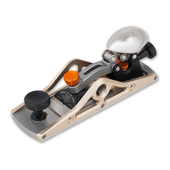
- Page 1 Bridge City HP-9v2 Dual Angle Block Plane Quality is contagious BRIDGE CITY TOOL WORKS...
-
Page 3: English Version
ENGLISH VERSION... - Page 5 The HP-9v2 Dual Angle Plane is a “bevel up” plane. This means that the iron bevel is visible from the top of the plane when bedded. The iron bed of the HP-9v2 plane is pitched 12° from the bottom (or “sole” ) of the plane.
- Page 6 The Iron The HP-9v2 Dual Angle Block Plane features an A2 tool steel iron which has been hardened to Rockwell 60-62. A2 is an air-hardened tool steel which contains a small percentage of chromium and molybdenum for added durability in cutting hard or soft woods.
- Page 7 Always use the magnetic iron guard on the end not being sharpened to prevent accidental injury. The iron included with the HP-9v2 Dual Angle Block Plane has been precision lapped to a .5 RMS finish. A typical glass mirror is a .5 RMS.
- Page 8 The iron clamping mechanism is controlled by the polished cap. When raising the cap, the clamp arm lifts out of the way unlocking the iron for removal. Moving the cap downward until it snaps will tighten the iron. Bevel up irons only need a small amount of pressure to keep the iron bedded without chatter during cutting.
- Page 9 Please follow the steps below to remove the iron: 1.Fully open the mouth by loosening the front tote and sliding the throat plate all the way forward and tighten. This helps to prevent nicking the iron on the throat plate. 2.Lift the cap until the clamping mechanism is raised to its highest position.
- Page 10 Rotating one knurled section to one of the semi-circular cuts next to it will increase/decrease the cut depth by 0.01mm. Iron Depth Fig. 5 Adjusting Cut Depth CAUTION: Always be careful to avoid crashing the iron into the throat plate. Adjusting Iron Cant The cutting edge of the iron is typically canted for two purposes;...
- Page 11 Mouth Adjustment The mouth opening is adjusted by loosening the front knob and moving the throat plate forward and backward. Take care not to hit the iron with the throat plate. Fig. 7: Mouth Adjustment The mouth opening should be just wide enough to allow shavings to escape, in order to minimize the chance of the wood splitting or tearing out ahead of the cutting.
- Page 12 Fig. 9: Brass Lead Screw Pivot Depth Skids The HP-9v2 Dual Angle Block Plane has a set of Depth Skids. These allow you to create accurate small pieces of wood that are the same thickness. The thickest piece of wood you could plane is 1-1/4” (about 32mm).
- Page 13 Attach the Depth Skids with the provided screws and washers. A washer goes between the screw head and Depth Skid. Then mount the Depth Skid sets to the sides with spacers in between. Fig. 11: Depth Skids Installation The easiest way to set up a hand plane for thickness planing is to use a set of Pin Gauges which come in .001”...
- Page 14 Fence The HP-9v2 Dual Angle Block Plane Fence has a square face and a 45-degree face. This allows you to plane edges that are either square or 45 degrees to the reference face of your stock. Attach the fence with provided fence posts and jam nuts, the hex locking studs and locking knobs are pre-installed in the fence.
- Page 15 The fence can be attached to either side of the plane body. You can choose to mount the square side of the fence to plane a perfect square side for a stock or mount the miter side of the fence for chamfering. Fig.
- Page 16 Wipe a thin coat of quality wax on the surface of the brass lead screw pivot to prevent the brass part from getting oxidization. Store: If you plan to store the HP-9v2 block plane for long periods, we recommend you wipe out the dust from the plane, lubricate all the moving parts and rub off...
- Page 17 Package Contains Plane body with all integrated components 42/27 Dual Edge Iron Magnetic blade guard Two Depth Skids and components Guide Fence and components Plane sock Instruction Manual...
- Page 18 中文版本...
- Page 19 HP-9v2 双角度短刨 恭喜您购买了 HP-9v2 双角度短刨。 在使用新短刨之前, 请阅读以下使用方法和 设置说明。 综述 HP-9v2 双角度短刨是一款刨刀正装的木工刨。 这意味着安装刨刀后, 可以从上 方观察到刨刀的斜面。 刨刀安装在与刨底呈 12° 的刨刀基座中。 刨底和可调节的喉板使用不锈钢材质制作, 两侧的侧边通过固定销与刨底连, 并且使用螺丝锁紧。 不要尝试取下刨身的侧边, 拧松螺丝后也无法拆除刨身侧 边。 刨刀通过四连杆结构压紧。 这些部件使用铝材通过 CNC 加工中心制作, 表 面通过阳极氧化处理非常美观, 并且几乎与钻石硬度相同。 刨刀压紧机构 刨刀 刨刀调节机构 深 度 导 向 板 组件 本体...
- Page 20 刨身的侧边简化设计后获得了优美的设计, 这与传统的根据欧洲早期设计改 良的短刨外观有明显的不同。 HP-9v2 双角度短刨真正是一款独特的, 并且可 以让大多数使用者在使用中获得快乐的短刨。 刨刀 HP-9v2 双角度刨刀配有一把工具钢刨刀, 通过硬化处理达到洛氏硬度 60-62。 工具钢通过气冷硬化, 并且含有铬、 钼和钨用于增加硬度, 更加适合硬木和软 木。 刨刀两端分别有一个刃口。 一端为 30°(25°主斜面与 5 度微角); 另一端为 35°(30°主斜面与 5°微角)。 角度较低的刃口斜面比角度较高的稍长一些, 这可 以帮助你快速判断刃口角度。 图 2:刨刀角度几何图示 当刨刀安装在 12°的基座内, 实际的刨削角度为 42°与 47°。 图 3:刨削角几何图示 42°的刨削角更适合用于刨削端面纹理和直纹纹理。 更高的 47° 刨削角则更适...
- Page 21 如果你不具备高超的手工磨刀技能, 使用磨刀器是非常好的选择。 在磨刀石 必须将刨刀刃口护罩安装在非打磨端, 防止出现意外伤害。 HP-9v2 双角度短刨使用的刨刀已经经过精密研磨, 刨刀背面的平面度为 0.5RMS, 从而达到镜面效果。 因此不再需要研磨刨刀背面。 我们推荐使用皮磨板去除研磨微角时产生的卷刃。 使用磨刀石研磨刨刀背面 会产生划痕, 将精密研磨的平面度降级。 刨刀压紧机构 HP-9v2 双角度短刨使用了非传统的, 独特的刨刀压紧机构。 理解如何调节这 个机构非常重要, 从而可以避免对零件造成损坏。 图 4: 非锁紧状态下的刨刀压紧机构 刨刀压紧机构通过镜面抛光的把手压盖控制。 提升把手压盖, 压紧杆则会跟 随提升释放刨刀, 从而可以将刨刀取出。 将把手压盖下压直到出现 “咬合” , 则 意味着刨刀已经压紧。 刨刀正装的结构只需要很小的压力即可保证在刨削时刨刀在基座中不出现 抖动。 当刨刀压紧力正确调节时, 不需要送开刨刀压紧机构, 就可以通过刨刀...
- Page 22 刨刀压紧机构在出厂前已经正确调节。 如果需要调节, 请按照如下方法: 1. 提升把手压盖从而提高压紧杆; 2. 逆时针旋转刨刀压紧旋钮, 完全释放刨刀压紧力; 3. 安装刨刀, 并且完全下压把手压盖; 4. 顺时针旋转刨刀压紧旋钮直到感觉到阻力; 5. 再旋转 1/4 圈则可以压紧刨刀。 这个压力可以保证在刨削时刨刀不发生偏 移。 注意:不要过度压紧这个结构, 不然可能会导致压紧杆出现永久变形而导致损 坏。 变形的压紧杆表明工具被滥用, 并且不再享受质保。 刨刀的拆除与安装 注意:刨刀非常锋利, 小心拿放刨刀防止出现意外伤害。 请按照如下方法拆除刨刀: 1. 拧松刨头处的喉板锁紧旋钮并滑动喉板完全打开刨口, 再 锁紧。 防止刨刀 刃口与喉板碰撞; 2. 提升把手压盖直到压紧杆升至最高位置; 3. 从上部抓住短刨, 并且食指压住刨刀;将短刨完全反转, 这时刨刀会安全的 掉落在手上,...
- Page 23 刨刀调节 刨刀刨削深度和偏摆(刨削倾角)可以通过把手压盖下方的调节丝杆完成。 在 使用中我们发现使用手指直接调节刨刀偏摆更加方便。 调节刨削深度 调节丝杆在 10mm 内有20个螺牙。 顺时针完全转动一圈增加0.1mm (0.004” )的刨削量。 逆时针旋转减小刨削量。 丝杆的调节旋钮处有五处滚花。 滚花既可以帮助抓握调节, 通过与凹处结合 可以形成十个定位块, 从而完成极其精细的调节。 将滚花处旋转至凹处可以 增加或减少 0.01mm 的刨削量。 刨削深度 图 5:调节刨削深度 注意:调解时避免刨刀与喉板碰撞。 调节刨刀偏摆 刨刀的刃口偏摆调节有两个目的:产生完全一致的刨削厚度或完全不一致的 刨削厚度。 前者是为了纠正磨刀产生的误差, 后者是为了解决刨削木料时单 边刨削过厚的问题。 反转短刨将刨底朝上, 左右摇动调节丝杆, 然后观察底部与刨刀检查刨刀偏 摆是否设置正确。 你可能会发现使用手指调节刨刀偏摆更加方便。...
- Page 24 图 6:调节刨刀偏摆 刨口调节 拧松刨头处的喉板锁紧旋钮, 并且前后滑动调节喉板位置。 注意防止喉板与 刨刀接触。 图 7: 刨口调节 刨口的宽度应正好允许刨花穿过, 减小木料在刨削时出现的撕裂。 当调节刨 口时需要注意刨刀偏摆时刨削量较大的一侧。 丝杆间隙调节 丝杆的间隙可以通过黄铜丝杆枢轴上方的两个调节旋钮控制...
- Page 25 丝杆间隙调节旋钮 图 8: 丝杆间隙调节旋钮 旋转旋钮锁紧黄铜枢轴消除丝杆回退间隙。 调节后确保上半部的黄铜枢轴与 下半部相对平行。 丝杆在旋转过程中应该感觉顺滑没有抖动。 黄铜枢轴 图 9: 黄铜枢轴...
- Page 26 HP-9v2 双角度短刨配有一对深度导向板。 这可以让你准确的制作相同厚度 的木质零件。 你可以制作的最后的木料是 32mm(大 约 1-1/4” )。 图 10: HP -9v2 双角度短刨与深度导向板 使用提供的螺丝和垫片安装深度导向板。 将垫片安装在螺丝与深度导向板, 再将垫块安装在深度导向板与刨身侧边间的螺丝上。 图 11: 安装深度导向板...
- Page 27 使用一套增量为 0.001” 或 0.01mm 的针规设置刨削厚度是最简单的方法。 先刨削木料的一面。 如果想制作 1/4” (6mm)厚的木料, 取出 0.260” (6.22mm)和 0.261” (6.20mm)的针规, 并且放置在干净的表面。 将较低的那 个放在刨头下方, 将较高的那个放在刨底后侧。 调节深度导向板并将他们完 全落在台面。 当深度导向板设置正确 时, 取下针规后刨子无法摇动。 刨削工件 直到没有刨花出现。 根据实际的刨刀深度和所需厚度选择正规进行另一面的 刨削。 靠山 HP-9v2 双角度短刨的靠山一面为直角一面为 45°角。 这可以让你完成任何直 角或 45°角边的刨削。 使用提供的靠山支架和锁紧螺母安装靠山。 图 12: 安装靠山...
- Page 28 请按照如下方法安装靠山: 1. 将锁紧螺母旋如靠山支架; 2. 将靠山支架安装至刨身侧边; 3. 反向旋转锁紧螺母并将螺母与刨身侧边锁紧; 4. 将靠山滑入靠山支架, 并且根据刨削需求定位靠山; 5. 锁紧靠山上的定位锁紧旋钮。 靠山可以安装在刨身的任何一侧。 你可以选择安装靠山的直角边进行完美 的直角边刨削, 也可以选择安装 45°角边用于木料倒角。 图 13: 靠山使用实例...
- Page 29 维护和保养 刨刀: 如果长时间不使用刨刀, 或储存在高潮湿环境中, 请在刨刀表面涂抹一 层很薄的油脂或 WD-40。 在每一次磨刀后使用干净的布擦除指纹。 刨底: 使用前在刨底擦拭一层很薄的高质量蜡或石蜡。 刨刀调节机构:每年一次或根据使用频率在丝杆上面。 黄铜枢轴中心: 丝杆前端的刨刀定位销内孔中滴入一滴轻质机油防止出现过 度磨损。 在黄铜枢轴外部擦拭高质量蜡防止黄铜部件出现氧化变色。 储存: 如果需要长时间储存 HP-9v2 双角度短刨, 我们推荐擦除短刨上的木屑 与灰尘, 润滑所有运动零件并且擦除多余的油脂和指纹。 将短刨装入塑料袋 内密封, 防止出现生锈。 并且将短刨放 置的安全的位置储存。 质保 所有退货、 换货、 技术服务和支持均由经销商的客户服务机构负责。 如果在原始购买日期后一年内发现工具存在工艺缺陷(客户无过失), 请与经 销商客户服务机构取得联系, 并由该服务机构决定 是否对工具进行修理或更 换。...
- Page 30 产品包含 短刨本体 42/47 双角度刨刀 刨刀刃口护罩 一对深度导向板与配件 靠山与靠山支架 短刨布套 说明书...
- Page 32 质保 所有退货、 换货、 技术服务和支持均由经销商的客户服务机构负责。 如果在原始购买日期后一年内发现工具存在工艺缺陷(客户无过), 请与经销商 客户服务机构取得联系, 并由该服务机构决定是否对工具进行修理或更换。 Bridge City Tool Works www.bridgecitytools.com...
Need help?
Do you have a question about the HP-9v2 and is the answer not in the manual?
Questions and answers