Table of Contents
Advertisement
Quick Links
Advertisement
Table of Contents

Subscribe to Our Youtube Channel
Related Manuals for PL Engineering DX4085

Summary of Contents for PL Engineering DX4085
- Page 1 PL Engineering Ltd. Z-METER DX4085 USER GUIDE Moscow, 2020 version 1.02...
- Page 2 Copyright All rights reserved. Reproduction in any manner, in whole or in part is straightly prohibited without written permission of PL Engineering Ltd. The information contained in this document is the subject to change without notice. page 2 of 63...
-
Page 3: Warranty
If the Z-Meter fails during the warranty period PL ENGINEERING will repair the Z-Meter or replace it or its parts. For the warranty support a Consumer can address to the office of the company PL ENGINEERING or its sales representative. -
Page 4: Table Of Contents
PL Engineering Ltd Z-Meter DX4085/ User Guide CONTENTS Warranty ..................3 Technical support ................3 1. Introduction ................. 7 2. Technical characteristics ............9 2.1. Specifications 2.2. Delivery Kit 2.3. Design overview 3. Preparations for working ............12 3.1. Charging battery 3.2. - Page 5 Z-Meter DX4085/ User Guide PL Engineering Ltd 6.5.3. Make the pre-sets for measurements 6.5.4. Measurements 6.5.5. Measurement results 7. Software ..................35 7.1. Introduction 7.2. Main Window 7.2.1. Menu Bar 7.2.2. Reference Bar 7.2.3. Functional Fields 7.3. Measurement Presets 7.3.1.
- Page 6 PL Engineering Ltd Z-Meter DX4085/ User Guide page 6 of 63 ver.1.02 (2020)
-
Page 7: Introduction
Z-Meter DX4085/ User Guide PL Engineering Ltd INTRODUCTION The portable Z-Meter provides measurement performance operational operating parameters thermoelectric (TE) modules. measure operation and performance thermoelectric cooling modules, thermoelectric generators, and thermoelectric sensors. The performance parameters are the following: AC Resistance ( ��... - Page 8 PL Engineering Ltd Z-Meter DX4085/ User Guide With the device it is also possible to test thermoelectric generators and sensors: voltage at thermoelectric generator (TEG) provided by temperature difference; response of thermoelectric heat flux sensor ADVANTAGES FEATURES Express testing ...
-
Page 9: Technical Characteristics
Z-Meter DX4085/ User Guide PL Engineering Ltd TECHNICAL CHARACTERISTICS 2.1. Specifications Parameters Values nits Electrical Resistance �� Range 0.1...100 Accuracy 0.6 (but>0.01Ohm) Repeatability �� Figure-of-Merit Range 1...3 Accuracy Repeatability Time Constant �� Range 1...100 Accuracy Repeatability Voltage (DC) Range -20…+20 Accuracy 0.02... -
Page 10: Delivery Kit
PL Engineering Ltd Z-Meter DX4085/ User Guide Parameters Values nits AC Voltage 110...240 Frequency 50/60 Voltage DC Power (max) Operational Conditions Temperature range ° +15...+35 С Humidity 0...95 Storage Temperatures range °C -20…+60 Humidity 5…95 Mechanical Parameters General Unit Dimensions 70х160х21... -
Page 11: Design Overview
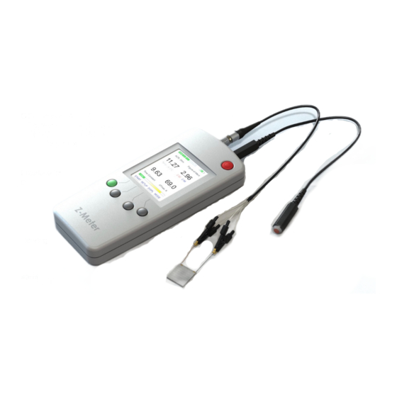
Z-Meter DX4085/ User Guide PL Engineering Ltd 1 pc. Z-meter unit 1 pc. Temperature sensor 1 ps. Measuring terminal* 1 pc. USB cable 1 pc. AC/DC power adapter * Measuring terminals can be supplied optional on the basis of Kelvin clips of various designs. -
Page 12: Preparations For Working
PL Engineering Ltd Z-Meter DX4085/ User Guide PREPARATIONS FOR WORKING Before very first use of the device we recommend to charge battery of the device to 100%. Details are in chapter “Battery charge procedure” Before routine switch ON the device connect the measuring probes and external temperature sensor –... -
Page 13: Connections
Z-Meter DX4085/ User Guide PL Engineering Ltd Connect cable to USB port of device and other connector to AC-DC adaptor. Charging status is placed in to top-right of status line and the main screen. Additionally LED near USB port indicate status of charging. - Page 14 PL Engineering Ltd Z-Meter DX4085/ User Guide to corresponding connectors on top side of device housing/ Connection of measuring probes Connection of temperature sensor Attention! Do not connect or disconnect external temperature sensor during device is ON. page 14 of 63...
-
Page 15: Te Module Connections
Z-Meter DX4085/ User Guide PL Engineering Ltd Note! If temperature sensor is not connected then all following measurements to be related to standard temperature – default value 300K. 3.3. TE module connections Examining TEC must be contacted to working devices by measuring probes and (in particular case) –... -
Page 16: Device Interface
PL Engineering Ltd Z-Meter DX4085/ User Guide Attention! Dump is possible in any status of device if to push the power button for 5 seconds. . DEVICE INTERFACE Device main windows onto 2.4’ TFT screen consists of three areas: top status string; large working area and bottom command string connected with command buttons. -
Page 17: Operation Modes
Z-Meter DX4085/ User Guide PL Engineering Ltd are indicated by bottom command string. 4.2. Operation modes The device provides the following modes of operation: Main Mode - measurement of TEC performance parameters (Figure-of-Merit, AC resistance, time constant), calculated capacity is calculated, ambient temperate is measured (if temperature sensor is connected) ... -
Page 18: Main Mode
PL Engineering Ltd Z-Meter DX4085/ User Guide Note! Main mode is default on device switch 4.4. Main Mode Main mode provides measurement of thermoelectric module performance parameters. AC Resistance ( �� page 18 of 63 ver.1.02 (2020) -
Page 19: Set Of Measuring Parameters
Z-Meter DX4085/ User Guide PL Engineering Ltd Figure-of-Merit ( �� Time Constant ( Maximum Temperature Difference ( ∆�� This is relatively long procedure takes up to minute or more. Note! Make sure that before the testing... -
Page 20: Measurements
PL Engineering Ltd Z-Meter DX4085/ User Guide Press the button and retrieve setting windows of the above mentioned parameters one by one. Select required value by buttons “<” and “>”. After set of required value press <SET> and come to the another parameter by <SETUP>... - Page 21 Z-Meter DX4085/ User Guide PL Engineering Ltd (selected total measuring time). Colored bar at the bottom of screen indicates progress of the measurements – yellow color. During measurements and after finish, it is possible to change screen from general view of measurement of all the parameters in the cycle to particular parameters.
-
Page 22: Measurement Of Ac Resistance
PL Engineering Ltd Z-Meter DX4085/ User Guide 4.5. Measurement of AC Resistance Note! Make sure that before the testing thermoelectric module is correspondingly connected to measuring probe and external temperature sensor is placed correctly – see chapter “TE module connections”. - Page 23 Z-Meter DX4085/ User Guide PL Engineering Ltd Start the measurement by button <START>. Result will be indicated with two values: • Top value – AC resistance measured as is at ambient temperature measured by temperature sensor. • The bottom value – recalculated AC resistance to standard reference temperature 27°C (300K).
-
Page 24: Measurement Of Operating Voltage And Temperature
PL Engineering Ltd Z-Meter DX4085/ User Guide 4.6. Measurement of operating voltage and temperature This is useful mode which provides measurement of operating voltage at thermoelectric modules. It is important information for testing of: • Operating voltage of thermoelectric cooling module in an application. -
Page 25: Additioonal Messages
Z-Meter DX4085/ User Guide PL Engineering Ltd ADDITIOONAL MESSAGES resistance measurement mode. Measured resistance is high and comes out of specification Measured resistance is low and comes out of specification At switch ON the device The temperature sensor is not... -
Page 26: Worwing With Remote Computer
PL Engineering Ltd Z-Meter DX4085/ User Guide WORWING WITH REMOTE COMPUTER The device has option of connecting with computer and measuring on operating software. The operating software provides some additional useful options of measuring: • storage of measurement results, •... -
Page 27: Software Installation
Z-Meter DX4085/ User Guide PL Engineering Ltd USB Serial Converter should appear in the Windows Device Manager after successful installation. 6.3. Software Installation Insert the CD/flash to a PC and start the Setup program. The window of the standard Windows installer will appear – see below. -
Page 28: Measurements
PL Engineering Ltd Z-Meter DX4085/ User Guide Connect Z-meter to USB port of your PC. To select this operation mode press command button <MODE> for about 5 seconds. Connect by microUSB cable the device with USB port of computer. 6.5. - Page 29 USB driver installation procedure if required (see 6). The main window will appear: Important! TEC polarity check option must be switched off (See “Software”). The Z-Meter type DX4085 does not support the option. ver. 1.02 (2020) page 29 of 63...
-
Page 30: Te Modules Connection
PL Engineering Ltd Z-Meter DX4085/ User Guide 6.5.2. TE Modules Connection Connect your TEC firmly as shown below. Ensure minimum possible air convection in the area of measurement. It is recommended to place the TEC as close to the Z-meter as possible keeping internal chamber opened. Remember temperature sensor is located in the chamber and considerable difference of TEC and thermosensor’s temperature will result in... - Page 31 Z-Meter DX4085/ User Guide PL Engineering Ltd In the case software will extract default corrections factors for the particular TEC type in the field of corrections If type is unknown then the state is “Default”. If the TEC type is not listed into software database one can stay correction coefficient as 1 (One), or to set own corrections coefficients if they are known of can be calculated.
-
Page 32: Measurements
PL Engineering Ltd Z-Meter DX4085/ User Guide beginning. Time of measurement Set the total measurement time. Recommended value – more than 5…6 of time constant of the TEC. If the value is unknown set stay default – 10 second for the beginning. -
Page 33: Measurement Results
Z-Meter DX4085/ User Guide PL Engineering Ltd After two curves appear (direct and reversed current measurement) the software will calculate all measured parameters TECs and Z-meters must be kept at ambient conditions expected during tests for at least of one hour before any measurement. - Page 34 PL Engineering Ltd Z-Meter DX4085/ User Guide Submenu "Export" will help you to keep a «History» file in various formats: More detailed descriptions of working with results and with software are described in Article – “Software” page 34 of 63...
-
Page 35: Software
Z-Meter DX4085/ User Guide PL Engineering Ltd SOFTWARE 7.1. Introduction The Z-meter must be plugged-in to PC before running the Program. The following windows will be displayed one after another in case you run Z-meter program for the first time, see below: If the “DEVICE NOT FOUND”... -
Page 36: Menu Bar
PL Engineering Ltd Z-Meter DX4085/ User Guide Its functional structure is the same for three Z-Meter measurement options: Single-stage TE module; Single-stage TE sub-mount; Two-stage TE module. 7.2.1. Menu Bar There are four items in the Menu bar. -
Page 37: Functional Fields
Z-Meter DX4085/ User Guide PL Engineering Ltd The field "Cooler type ID" allows selecting a TE module type to be tested. The field "Reference T" serves for the reference temperature input. The values displayed will be �� ∆�� recalculated to this temperature. The temperature step is 0.1 K. - Page 38 PL Engineering Ltd Z-Meter DX4085/ User Guide voltage U(t) temporal behavior telemetry. It also indicates obtained values of: Time constants at different current polarities, Z at different current polarities Corrections field shows the important calculated corrections values which will be used for calculation of them main performance parameters like, for example, (see Chapter 9.3...
-
Page 39: Measurement Presets
Z-Meter DX4085/ User Guide PL Engineering Ltd Manual - using a User's own coefficient value A, manually inputted; None – no use of any correction. Results field contains the following measured/calculated results: Electrical AC resistance of the TE module;... -
Page 40: Te Module Type
PL Engineering Ltd Z-Meter DX4085/ User Guide Attention! The standard temperature is 27°C, other manufacturers may apply their own values. The most convenient ambient temperature to which the parameters are recalculated may be selected from a “Reference T” list of entered manually. -
Page 41: Correction Coefficients
Z-Meter DX4085/ User Guide PL Engineering Ltd field will change to DEFAULT in this case. 7.3.3. Correction Coefficients With all TEC parameters available, the corrections as well as their equivalent coefficient А are taken into account by default (see Equation 9.3.3.1). The corrections are specified in the Table below. -
Page 42: Measurement Procedure And Notes
PL Engineering Ltd Z-Meter DX4085/ User Guide header material thermal conductivity; header base thickness; mounted TE module fully described in the Z-meter database. 7.4. Measurement Procedure and Notes Measurement cycle is started simply clicking “Measure” in the Program Main Window. - Page 43 Z-Meter DX4085/ User Guide PL Engineering Ltd Note the last case is hardly possible in practice according to PL ENGINEERING’s experience. Therefore, open circuit is more likely the reason. Double-check the terminals for proper contacting TEC. Retry measuring. Occurring of the message indicates on TE module failure/malfunction.
-
Page 44: History
PL Engineering Ltd Z-Meter DX4085/ User Guide 7.5. History 7.5.1. File The results of each measurement are stored in the file. You can view or clear it using the "File" command. The history file is created in the "/History" folder of the "/Z-meter"... -
Page 45: Options
Z-Meter DX4085/ User Guide PL Engineering Ltd The "Chk" field is assigned for records marking. Note only marked records will be copied on a printer under the "Print" command. The marking/unmarking is performed with the mouse left button click on the appropriate field. -
Page 46: Te Modules Database Update
PL Engineering Ltd Z-Meter DX4085/ User Guide The example of Preview Report is shown below. 7.6. TE Modules Database Update If the parameters of any TE module are not available in the database, you can add them by yourself. The full set of parameters consists of: TE module cold and hot sides dimensions;... - Page 47 Z-Meter DX4085/ User Guide PL Engineering Ltd Leading wires cross-section. Choose the database you want to change (see the figure above, example only). Select the "File" -> "TEC Base Editor" command from the "Main" menu. The window titled "Add TE cooler" will appear.
-
Page 48: Maintenance
PL Engineering Ltd Z-Meter DX4085/ User Guide The contents of "Cooler ID" field are not used for calculations. You can fill any information in this field. You can also edit or delete a TE module existing in the database. To do it just select the TE module, make appropriate changes in the data and click on the "Add/Modify"... - Page 49 Z-Meter DX4085/ User Guide PL Engineering Ltd Compare the data obtained. If the difference in the resistance values is within 0.5%, the Z-Meter can be further used for measurements. ver. 1.02 (2020) page 49 of 63...
-
Page 50: Appendix 1. Theoretical Groundings
PL Engineering Ltd Z-Meter DX4085/ User Guide APPENDIX 1. THEORETICAL GROUNDINGS 9.1. Time Constant Let us consider a single-stage TE module. The ambient temperature . At a certain moment electric current is applied to the module. �� The differential equation describing transient dynamics for a pellet of... -
Page 51: Interpolation Results
Z-Meter DX4085/ User Guide PL Engineering Ltd ���� �� �� = (9.1.3) ������ (�� + �� ) 1 + �� �� �� �� Where - TE module cold side and hot side heat capacities, �� �� - TE material Seebeck coefficient, ��... - Page 52 PL Engineering Ltd Z-Meter DX4085/ User Guide Note! TE module time constant is the time during �� which TE module temperature difference grows ∆�� from 0 to 0.63 is steady state value) at ∆�� �� ∆�� electric current turned on.
-
Page 53: Figure-Of-Merit Z
Z-Meter DX4085/ User Guide PL Engineering Ltd 9.3. Figure-of-Merit Z 9.3.1. Single-stage TE Module �� Among the parameters ( , ��), measured by the Z-Meter �� �� ∆�� the AC resistance is the only measured directly. The �� �� measurement method is described in the Section "AC Resistance Measurement". - Page 54 PL Engineering Ltd Z-Meter DX4085/ User Guide - electric current, �� - electric resistance of a TE module pellet, �� - TE module cold side temperature, �� - TE module hot side temperature, �� - ambient temperature, �� - TE module pellets number, ��...
-
Page 55: Two-Stage Te Module ��
Z-Meter DX4085/ User Guide PL Engineering Ltd - TEC Seebeck voltage, �� = ����(�� − �� ) - TEC Ohmic component of the voltage. �� = ������ The ratio of the voltages in Eq. (9.3.1.5) must be averaged �� ��... - Page 56 PL Engineering Ltd Z-Meter DX4085/ User Guide Here are heat rate equations for a two-cascade TE module: �� ′ ������ − �� �� − �� �� − �� (�� − �� ⎧ �� �� ⎪ �� ⎪ ′ ������ ��...
-
Page 57: Alternative Correction
Z-Meter DX4085/ User Guide PL Engineering Ltd we obtain: �� (9.3.2.5) �� = (1 + �� + �� + �� ) �� �� Attention! In real testing Eq. ( 9.3.2 .4) is not rigorous, ( 9.3.2 .5) is only a relative criterion of a TE ��... - Page 58 PL Engineering Ltd Z-Meter DX4085/ User Guide periodically (with 50% duty circle) reverses a circuit of the reference current . The “Commutator’s” simplified diagram is shown below. �� If there is no input signal, the output voltage of the instrumentation amplifier equals to ⁄...
-
Page 59: The �� And ���� Telemetry
Z-Meter DX4085/ User Guide PL Engineering Ltd where voltage gain of the instrumentation amplifier; �� - total number of readouts per measurement. �� Typical values of parameters in formula (10.1.1) are: = 2 mA, �� = 5 or 50, ��... - Page 60 PL Engineering Ltd Z-Meter DX4085/ User Guide the voltage values referred to the time at which the process becomes steady. The Seebeck voltage in (9.3.1.5) and (9.3.2.5) is equal to the �� stationary value obtained by the interpolation procedure (see ��...
- Page 61 Z-Meter DX4085/ User Guide PL Engineering Ltd ver. 1.02 (2020) page 61 of 63...
- Page 62 PL Engineering Ltd Z-Meter DX4085/ User Guide page 62 of 63 ver.1.02 (2020)
- Page 63 Z-Meter DX4085/ User Guide PL Engineering Ltd Overseas Sales representative PL Engineering Ltd. TEC Microsystems GmbH 46 Warshawskoe shosse Schwarzschildstrasse 8 Moscow 115230 Russia Berlin 12489, Germany e-mail: info@promln.com phone: +49-(0)30-6789-3314 phone: +7-499-678-3231 fax: +49-(0)30-6789-3315 fax: +7-499-678-3258 e-mail: info@tec-microsystems.com website: www.promln.ru website:www.tec-microsystems.de...
Need help?
Do you have a question about the DX4085 and is the answer not in the manual?
Questions and answers