Advertisement
Quick Links
Circuit diagrams
V+
R4
220
R1
47K
Transistor
Q1
R2
0V
Dark activated version
V+
R4
220
R1
Transistor
R2
Q1
47K
0V
Light activated version
Technical specification
Supply Voltage
+
Minimum
LED1
Maximum
A supply voltage of 3V to 5V allows for better adjustment.
Output
Output voltage
R3
Vout
-
Output current
Maximum
Guidance note
You should ensure that you have a stable power source when
Transistor
using the output to switch on high output loads. This is because
Q2
if the power source is unable to provide enough power this may
result in a supply voltage dip and cause output to switch off. At
this point the voltage is likely to recover and turns the output on
again. The output would then be in state where it is rapidly
switching on and off.
+
LED1
Output
R3
4
-
4
www.kitronik.co.uk/quicklinks/2112/
Transistor
Description
Q2
Light activated switch kit
Email:
Web:
Tel:
Fax:
= 3V
= 12V
= Supply voltage less 0.9V
= 0.5A
53
4 x 3.3mm diameter mounting holes
Code
2112
sales@kitronik.co.uk
www.kitronik.co.uk
0845 8380781
0845 8380782
Light activated switch kit
Stock code 2112
25
Example boat that automatically stops when it enters a
dark tunnel, made by Fernwood Comprehensive School
Build instructions & circuit description
More information is available on the Kitronik
website or on the school resources CD
Advertisement

Related Manuals for Kitronik 2112

Summary of Contents for Kitronik 2112
- Page 1 Example boat that automatically stops when it enters a dark tunnel, made by Fernwood Comprehensive School Email: sales@kitronik.co.uk Light activated version Build instructions & circuit description Web: www.kitronik.co.uk Tel: 0845 8380781 More information is available on the Kitronik Fax: 0845 8380782 website or on the school resources CD...
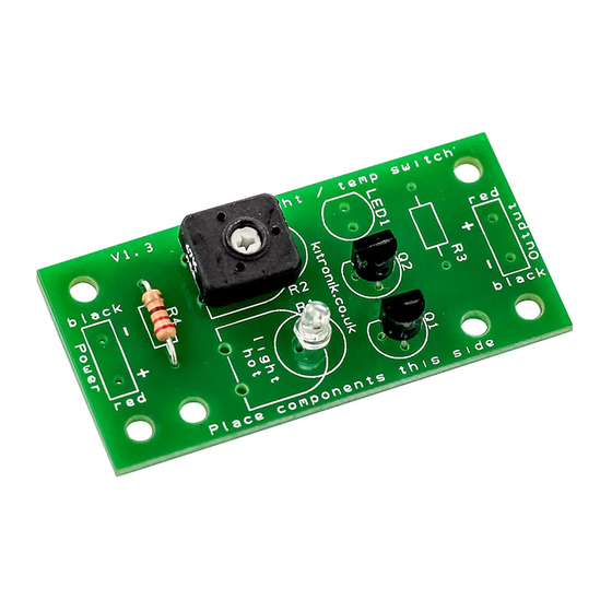
- Page 2 Build Instructions External connections Checking your PCB Before you start take a look at the Printed Circuit Board (PCB). Connecting power Check the following before you connect power to the board: The components go in the side with the writing on and the There are two power terminals on the PCB to allow power to be solder goes on the side with the tracks and silver pads.
Need help?
Do you have a question about the 2112 and is the answer not in the manual?
Questions and answers