
Related Manuals for Edgetech STARMUX III

Summary of Contents for Edgetech STARMUX III
- Page 1 STARMUX III U S E R H A R D W A R E M A N U A L 0016903_REV_B July 2016 EdgeTech 4 Little Brook Road West Wareham, MA 02576 Tel: (508) 291-0057 Fax: (508) 291-2491 www.EdgeTech.com...
- Page 2 The information, figures, and specifications in this manual are proprietary and are issued in strict confidence on condition that they not be copied, reprinted, or disclosed to a third party, either wholly or in part, without the prior, written consent of EdgeTech. Any reproduction of EdgeTech supplied software or file sharing is strictly prohibited.
-
Page 3: Attention - Read This First
ATTENTION – READ THIS FIRST! All personnel involved with the installation, operation, or maintenance of the equipment described in this manual should read and understand the warnings and cautions provided below. CAUTION! This equipment contains devices that are extremely sensitive to static electricity. -
Page 4: Hardware Variations And Compatibility
HARDWARE VARIATIONS AND COMPATIBILITY The STARMUX III contains both standard and proprietary hardware. At times, EdgeTech may change the standard components due to their availability or performance improvements. Although the component manufacturers—along with their models and styles—may change from unit to unit, replacement parts will generally be interchangeable. -
Page 5: About This Document
ABOUT THIS DOCUMENT We, the employees at EdgeTech, would like to thank you for purchasing STARMUX III. At EdgeTech, it is our policy to provide high-quality, cost-effective products and support services that meet or exceed your requirements. We also strive to deliver them on-time, and to continuously look for ways to improve them. -
Page 6: Warranty Statement
All equipment manufactured by EdgeTech is warranted against defective components and workmanship for a period of one year after shipment. Warranty repair will be done by EdgeTech free of charge. Shipping costs are to be borne by the customer. Malfunction due to improper use is not covered in the warranty, and EdgeTech disclaims any liability for consequential damage resulting from defects in the performance of the equipment. -
Page 7: Software Service Overview
Software Updates and Enhancements EdgeTech customers can download new software releases with all modifications and enhancements from the EdgeTech ftp site. Major software issues, should they occur, will be reported directly to the customer. New software releases consist of the following: ... -
Page 8: Returned Material Authorization
RETURNED MATERIAL AUTHORIZATION Prior to returning any equipment to EdgeTech, a Returned Material Authorization (RMA) number must be obtained. The RMA will help us identify your equipment when it arrives at our receiving dock and track the equipment while it is at our facility. The material should be shipped to the address provided in the section. - Page 9 4. Small items can be shipped prepaid directly to EdgeTech by FedEx, DHL, UPS, Airborne, etc. 5. If the equipment is the property of EdgeTech (formerly EG&G Marine Instruments Division), please insure for full value. 6. Fax one invoice, packing list, and a copy of the airway bill to EdgeTech upon shipment.
-
Page 10: Customer Service
CUSTOMER SERVICE Customer service personnel at EdgeTech are always eager to hear from users of our products. Your feedback is welcome, and is a valuable source of information which we use to continually improve these products. Therefore we encourage you to contact EdgeTech Customer Service to offer any suggestions or... -
Page 11: Company Background
USBL positioning systems, and bathymetric systems—that have become standards in the industry. EdgeTech has also consistently anticipated and responded to future needs through an active research and development program. Current efforts are focused on the application of cutting-edge CHIRP and acoustic... -
Page 12: Table Of Contents
3.1 Unpacking and Inspecting ......................3-1 3.2 Installing the Digital Link ....................... 3-1 3.2.1 Controls, Indicators, and Connections ................... 3-1 3.2.2 Connecting the STARMUX III ....................3-2 3.3 Activating the Unit ........................3-2 3.4 Post-Recovery ..........................3-3 4.0: TECHNICAL DESCRIPTION ......................4-1 4.1 Internal Components ........................ - Page 13 xiii 6.0: TROUBLESHOOTING .........................6-1...
-
Page 14: List Of Figures
LIST OF FIGURES Figure 3-1: Front and Back Panels of STARMUX III ..................3-3 Figure 4-1: STARMUX III—Internal Components ..................4-3 Figure 4-2: STARMUX III—Block Diagram ....................4-4 Figure 4-3: STARMUX III—Wiring Diagram ....................4-5 STARMUX III 0016903_REV_B... -
Page 15: List Of Tables
LIST OF TABLES Table 2-1: STARMUX III Specifications ....................... 2-1 Table 6-1: STARMUX III Troubleshooting Guide ..................6-2... -
Page 17: Overview
1.0: OVERVIEW The STARMUX III Digital Link provides power for the towfish, while acting as an interface between an external topside processor and an EdgeTech tow vehicle such as a 4200, 2000-DSS, or 2000-TVD towfish. 1.1 Applications The STARMUX III unit can be used in conjunction with the systems above for the following applications: ... -
Page 19: Specifications
2.0: SPECIFICATIONS The specifications for the STARMUX III are shown in 2-1: ABLE SPECIFICATION VALUE Size: 8.3 cm (3.25 in) high 48.5 cm (19.0 in) wide 43.2 cm (17.0 in) deep Weight: 6.4 kg (14 lb) Case Type: EIA RS-310C 19-inch rack mount... -
Page 21: Setup And Activation
3.2 Installing the Digital Link Install the STARMUX III Digital Link in a standard 19” rack. This should be in an area free from sea spray, precipitation, and potentially-damaging UV rays (sunlight). Furthermore, the unit should be located in close proximity to the topside and in an area where the operator can see the deck crew deploying the towfish for easy communication. -
Page 22: Connecting The Starmux Iii
3.2.2 Connecting the STARMUX III Place the unit in a 19” rack as described in sub-section 3.2, then connect and plug in the STARMUX III power cable. Then connect the unit to the topside processor and any other data sources such as a navigation system. -
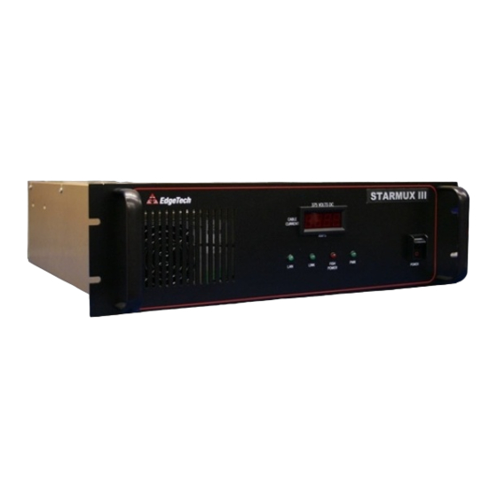
Page 23: Post-Recovery
Figure 3-1: Front and Back Panels of STARMUX III 3.4 Post-Recovery After recovering a tow vehicle from a survey, power down the topside processor and STARMUX III. The unit can then be safely disconnected from the tow vehicle. If the next survey is not for an extended period... -
Page 25: Technical Description
4.0: TECHNICAL DESCRIPTION This section provides an overall general description of the hardware elements of the STARMUX III DIGITAL LINK. This information, which includes block diagrams, board descriptions, chassis photos, component callouts, and wiring diagrams, can be useful for troubleshooting purposes and installing optional equipment. - Page 26 DC connector from the +12 VDSC Power Supply. FSIU The FSIU board mounts to the STARMUX III chassis. The FSIU connects between the Sea Cable Interface (FSIC) and the ADSL Modem in the STARMUX III chassis. The FSIU board inputs +24 VDC on J3 from the PS1 (24VDC) output to power the digital and analog circuitry.
- Page 27 FSIU Board Power Entry Module Sea Cable Interface Modem Board 375 V Power Supply 12 V Power Supply Power Switch Figure 4-1: STARMUX III—Internal Components...
- Page 28 COMPUTER NETWORK LAN ADSL MODEM ETHERNET ETHERNET 192.9.0.99 192.9.0.22 ADSL SEA CABLE ADSL FSIU PCB ADSL INTERFACE TOW VEHICLE (FSIC) SEA CABLE (ADSL) ADSL MODEM 192.9.0.23 TOPSIDE SONAR PROCESSOR 192.9.0.101 Figure 4-2: STARMUX III—Block Diagram...
- Page 29 Figure 4-3: STARMUX III—Wiring Diagram...
-
Page 31: Maintenance
5.0: MAINTENANCE The STARMUX III is rigidly build, and therefore requires little maintenance. Occasionally cleaning its cooling fan may prevent overheating after years of dust build-up and extend the life of the unit. Beyond this, no maintenance is required. - Page 33 LED and wiring. There is no connection between Check the LAN connections the digital link and the external between the STARMUX III unit The green LAN indicator does topside processor. and the topside processor. not illuminate when the unit is turned on.
- Page 34 (if used on external topside). address is 192.9.0.101 with “Port” set to 1700. Verify the tow vehicle using a different digital link. Verify the Tow vehicle is faulty. digital link with a different tow vehicle. Table 6-1: STARMUX III Troubleshooting Guide STARMUX III 0016903_REV_B...
Need help?
Do you have a question about the STARMUX III and is the answer not in the manual?
Questions and answers