Table of Contents
Advertisement
Quick Links
PDM II User Manual
Front Panel Overview
The Input Level Meter (A) monitors the signal going into PDM II's processing circuit. As they follow the A/D
converter in the signal path, they will accurately monitor the input regardless of the Input Sensitivity setting.
Note that this is a peak meter to be used as a diagnostic tool for setting input levels; it does not display RMS
voltage or a time-integrated level and is not intended to be a replacement for a more sophisticated loudness
meter.
Four dark LEDs: The input signal is below -36 dBFS.
One Green LED: The input signal is above -24dBFS.
Two Green LEDs: The input signal is above -18dBFS.
Three Green LEDs: The input signal is above -12dBFS.
Four Green LEDs: The input signal is above -6dBFS.
Top LED is Yellow: The input signal is above -0.5dBFS.
Top LED is Red: The input signal is above +0.5dBFS.
All LEDs are Yellow: The unit is expecting a Livewire input but not seeing a valid signal, or there is an
internal error.
PDM II
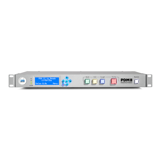
Figure 1 - Front panel controls
Advertisement
Table of Contents

Related Manuals for 25-Seven PDM II


Summary of Contents for 25-Seven PDM II
- Page 1 Figure 1 - Front panel controls The Input Level Meter (A) monitors the signal going into PDM II’s processing circuit. As they follow the A/D converter in the signal path, they will accurately monitor the input regardless of the Input Sensitivity setting.
-
Page 2: Rear Panel Overview
The LCD display (B) shows a variety of information about the current status of the PDM II and provides a menu system for front-panel setup and configuration. The navigation cluster (C) is made up of left, right, up, and down arrows plus a green "checkmark" button (generally used as an "Enter"... -
Page 3: Front Panel Menus
IEC AC power inlet (J) Front Panel Menus While PDM II offers a comprehensive HTML5 browser-based user interface, most of the setup, configuration, and operation of the unit can also be accomplished via the front panel controls. The front panel navigation cluster is made up of five buttons: Navigation cluster Left, Right, Up, and Down buttons, for navigating through lists and adjusting values;... -
Page 4: Audio Menu
Figure 1 - Configuration menu Many of the PDM II's menus contain more than four items, and so cannot be completely displayed on one screen. In this case, the extra items above or below the visible items (as indicated by the word "More") can be seen by scrolling with Up/Down arrows. -
Page 5: Audio Input
Figure 4 - Livewire receive channel screen Input Sensitivity When using an analog audio source, this value should be set to the absolute loudest level PDM II will see in your installation. The up/down arrows change the value. The "L" and "R" values represent the resulting digital levels for the incoming analog signal and can be used along with an externally generated test tone to adjust the sensitivity settings. - Page 6 The Analog Output Level screen displays how the analog output level reflects digital audio levels within PDM II's processor. With the setting as shown below, 0 dBFS within PDM II will yield a +14 dBu analog output. The output levels should generally be set to match the Input Sensitivity level, though levels can be adjusted to create a gain or loss at the analog outputs.
- Page 7 Figure 8 - AES output lock screen AoIP TX Type Audio over IP (AoIP) audio can be sent from PDM II as either a standard AES67 stream or as a Livewire stream. It can also be disabled if desired. Figure 9 - AoIP Tx mode screen AES67 Tx Address The multicast address of the AES67 transmit channel is set here.
-
Page 8: Controls Menu
Delay Size The Delay Size control determines how much delayed audio PDM II will store in its buffer. The up/down arrows set a value between a minimum of 1.0 second and the maximum as determined by the setting of the... - Page 9 Figure 5 - Build speed screen Max Speed The Max Speed screen sets a limit for how quickly PDM II can build or exit a delay. The Build Speed setting cannot be set faster than the value set here.
- Page 10 Insert - PDM II will play a station jingle, ID, or other fill material from its internal memory. Pre-roll - PDM II will mute its output while you play material from another source, or while it signals your automation system to play audio.
- Page 11 Compress - PDM II will play any remaining audio using time compression, subtly speeding up what's in memory to rejoin real-time faster. Roll Out - PDM II will stop adding audio to its buffer and play what's left in memory with no speed changes. This sometimes referred to as the "wait and exit" mode.
-
Page 12: System Menu
Figure 2 - Time and date screen Note - Having an accurate clock is important when using PDM II's PD-Alert function which uses date and time stamps to identify events and audio log files. - Page 13 The Password menu allows you to set and change the password required to access the web-based remote control. The PDM II ships with no default password. You must set a password via the front panel in order to access the unit remotely. The left/right arrows change the field while the up/down arrows change the value.
-
Page 14: Network Menu
LCD backlight. Figure 7 - Screen saver screen Network Menu The Network Menu contains the controls necessary for configuring PDM II's two network ports. Note that not all menu items will be visible with all configurations. Figure 1 - Network menu... - Page 15 PDM II contains two network interface controllers with rear-panel RJ45 Ethernet ports labeled "Primary" and "Secondary". The Primary port supports Power over Ethernet (PoE) and Livewire+/AES67. The Secondary port does not. The Primary port is always active. The Secondary port can be disabled if desired.
- Page 16 Figure 3 - NTP enable screen NTP Server Menu This menu allows you to enter the IP address of a local NTP server. If no address is entered (the server is set to 0.0.0.0), PDM II defaults to using "pool.ntp.org" servers.
- Page 17 GPIO Menu The GPIO menu allows you to program the hardware parallel inputs and outputs used to remotely control certain PDM II functions. Livewire GPIO is configured in the Configuration page of the web-based user interface. Figure 1 - GPIO menu The inputs and outputs are opto-isolated to easily interface with external equipment.
- Page 18 15 port is active. Figure 2 - GPIO Enable menu GPIO Inputs Each of the five input pins can be assigned a PDM II function. The same function can be assigned to multiple input pins. Figure 3 - GPIO inputs GPIO inputs can either be triggered or level-sensitive.
- Page 19 For example, if the network provides a contact closure to trigger a local break and its input is assigned to a Cue function, PDM II will generate a corresponding Cue output when that sample is reached in order to trigger external equipment to start the break.
- Page 20 state when the lamp is on, a "High" state when the lamp is off, and cycles on and off when the lamp is flashing. ExitLamp: Duplicates the front panel "Exit" button lamp. DumpLamp: Duplicates the front panel "Dump" button lamp. CoughLamp: Duplicates the front panel "Cough"...
-
Page 21: Information Menu
Basic Operation In short, the primary function of the PDM II is to create a buffer of delayed audio that ensures profanity or other objectionable audio doesn't make it to the air. Creating this buffer is called "building a delay."... - Page 22 Figure 2 - Post-bootup status screen Pressing the Bypass button brings up the Ready screen. PDM II has no delay at this point, which makes the transition from Bypass mode seamless. Figure 3- Ready screen Pressing the Build button begins building a delay, and the length of the delay will increase as the buffer builds.
- Page 23 Build button stops flashing while the Dump button remains lit. You can choose how long PDM II takes to build a delay. Choose a setting based on how quickly your talent talks, how subtle you want the time manipulations to be (slower speaking styles can work with higher speed settings), and how long you’re willing to wait for the delay memory to fill.
- Page 24 Dump button will light. You can also press the Dump button when it’s not lit. While PDM II won’t have enough audio stored to dump all of the seconds you’ve designated for a dump event, it will dump whatever it has available.
- Page 25 If the Exit Mode is set to "Roll Out", PDM II will stop storing new audio and play what’s in memory with no speed change. Some operators call this function "roll out" or "wait and exit".
- Page 26 Note that we exaggerate and stretch the text to better illustrate how PDM II adjusts audio speed. In actual use, PDM II’s functions are a lot more subtle and most listeners won’t be able to tell they’re in use. They’re also user-adjustable, so you can fine-tune the sound to your programming and station’s style.
- Page 27 Setting the Build Mode to "Insert" and pressing Build plays a pre-selected audio file from its internal storage. In this mode, the talent begins talking as soon as Build is pressed. PDM II sends the studio signal to its delay memory while the audio file plays out to the transmitter. When the audio file finishes playing, PDM II...
- Page 28 Multiple build files can be stored and selected as needed from the front panel or remote user interface. If the selected build file is exactly as long as the Delay Size, PDM II will smoothly join delayed audio at normal speed when the file finished playing. If the file is not the same length as the Delay Size, it will still join delayed audio when the file finishes but will subtly speed up or slow down the output as needed to achieve the specified pre-set delay.
-
Page 29: Cough Mode
Figure 5 - Cough mode Exit Modes When it is no longer necessary to delay program audio, PDM II can exit and return to real-time programming by Rolling Out or Compressing. Exit by Roll Out This is the traditional method of exiting delay, not dissimilar to the method used by old-fashioned tape delays. - Page 30 PDM II keeps recording audio into its memory. PDM II plays out everything in its memory at a slightly faster speed until it is empty and the output catches up with the input, at which point it drops into non-delay mode.
-
Page 31: Web-Based User Interface
GUI to function. If you are trying to connect to your PDM II over a WAN or across the Internet, you will need to use a NAT router to route ports 80 and 5444 to the unit's local IP address. - Page 32 Be sure to also set any necessary permissions in your firewall. Front Panel GUI Page PDM II can be operated remotely in exactly the same way as you would from the physical front panel by selecting the Front Panel tab.
- Page 33 Important - When using the web GUI to control a PDM II in another studio, always check to make sure the unit isn't in use and feeding audio to your program bus to avoid accidentally disrupting on- air programming. Note - Changes made at the PDM II's front panel while the web GUI is open will not be automatically reflected on the remote computer;...
- Page 34 II's as desired, click "Add", and enter the user name and password when prompted. As many as 20 panels can be displayed at once. The name of each PDM II (as set in the "Configuration" menu) will be displayed to help identify each specific unit.
-
Page 35: Configuration Page
Note - To avoid duplication, only the items unique to the web GUI will be explained in this section. Identification Section Each PDM II can be given a unique name of up to 19 characters including upper and lower case letters, numbers, and dashes. Spaces and special characters may not be used. - Page 36 Figure 2 - Boot mode Hardware GPIO Section Although hardware GPIO settings can be set from the front panel as described in the GPIO Menu section the duration of the pulse for momentary output closures can only be set in the Hardware GPIO section of the Configuration page.
- Page 37 RDS receives or web streams in sync with program audio. When this feature is turned on, incoming data is stored for exactly the same amount of time that PDM II is delaying audio before sending it out.
- Page 38 Figure 5 - Delayed data streams input PD-Alert Section When the operator presses the Dump button, PDM II can automatically e-mail text alerts or actual audio files to anyone you designate. For security purposes, configuration of the PD-Alert settings must be done from the web GUI.
- Page 39 30, 60, or 90 days instead, at which point PDM II will automatically delete files as they reach that age.
- Page 40 Figure 6- PD-Alert menu AoIP Synchronization When using a Livewire clock as the clock source, choose "Livewire slave" from the dropdown menu. Figure 7 - AoIP sync using Livewire clock When using an external PTP clock for reference, choose "PTP/IEEE 1588 slave" from the dropdown menu, which reveals several additional fields: PTP Domain: Valid values are 0 - 127.
- Page 41 Dump Archive Page Clicking on the Dump Archive tab lists all Dump files stored within PDM II. The most recent file is shown first. Files are built in pairs, one for the studio audio that got deleted (OffAir) and one for what the listeners actually hear (OnAir).
- Page 42 Unless you are using Overkill Mode (which covers the dumped material with an internal audio file of the same length), the OffAir file will be longer than the OnAir file. In the unlikely event that PDM II has zero delay available when the Dump button is pressed and you are not using Overkill Mode, both files will be identical in size and will contain only the pre- and post-Dump context audio.
- Page 43 Audio Files Page The Audio Files page manages which audio files will be played by PDM II during Insert Build Mode or Overkill Dump Mode. Files can be uploaded using the 'Choose File" button. Once uploaded, they can be renamed or deleted with the corresponding buttons, or auditioned by clicking on the file name.
-
Page 44: Information Page
When instructed to do so by Telos Alliance customer support, you may download log packages covering the last 5 days, last 30 days, or all stored logs. Maintenance PDM II can be rebooted remotely by clicking on the "Reboot Unit" button. An "Are you sure?" page will open for verification before the unit reboots. Information Page Clicking on the Information tab provides an abundance of data about PDM II including audio, networking, and time format statuses, hardware-specific information, and unique identification numbers. -
Page 45: Serial Remote Control
Requests and responses are standard ASCII characters, based on plain English, using familiar PDM II “front panel” designations whenever possible. Requests - messages from the controller to PDM II - consist of a number of words followed by a Line Feed character <LF> (ASCII 10). Messages are case-sensitive. Note that Carriage Return (ASCII 13) is ignored. - Page 46 Requests consist of a command (something for PDM II to do), usually followed by arguments (what it should act upon), and then a Line Feed <LF>. Commands include: down - Start the event described by <argument>. Used for level-sensitive inputs up - End the event described by <argument>.
- Page 47 Note 2: Output Event Messages (preceded by @) only appear after they have been specifically enabled for a type of event. Output Event Messages PDM II's Output Event messages can be used to build elaborate custom remote controls. Any event that can trigger a GPIO output can also be sent serially.
- Page 48 Each type of output event must be specifically enabled before PDM II will report it. This way, you can tell PDM II to report only those events that are important to your installation. When a socket connection is made to port 5443, a System Active message is sent: @Welcome to PDM.
- Page 49 Command The disable command turns off reporting of one or more output events and follows a similar syntax. disable DumpTrig<LF> tells PDM II to stop reporting that DUMP has been activated. disable DumptTrig Muted<LF> turns off reporting for both functions.
Need help?
Do you have a question about the PDM II and is the answer not in the manual?
Questions and answers