
Related Manuals for 25-Seven PDM


Summary of Contents for 25-Seven PDM
- Page 1 PROGRAM DELAY MANAGER Profanity Delay Reinvented Operator's Manual Version 2.4a • September 2019 p/n 2001-00350-000 Program Delay Manager - AES p/n 2001-00351-000 Program Delay Manager - LIVEWIRE TelosAlliance.com...
- Page 2 © 2019 TLS Corporation. All rights reserved. About 25-Seven Systems 25-Seven Systems specializes in audio technologies and products that address the unique problems of radio broadcasters, networks and content providers. The company was launched in 2003 by a group of veteran broadcasters with extensive audio experience and a significant portfolio of intellectual property.
- Page 3 Installation must be performed in accordance with all national wiring rules. Caution: DOUBLE POLE/NEUTRAL FUSING The PDM power supply incorporates an internal fuse. Hazardous voltages may still be present on some of the primary parts even when the fuse has blown. If fuse replacement is required, replace fuse only with same type and value for continued protection against fire.
- Page 4 Company. All other trademarks are the property of their respective holders. All versions, claims of compatibility, trademarks, etc. of hardware and software products not made by 25-Seven which are mentioned in this manual or accompanying material are informational only. 25-Seven makes no endorsement of any particular product for any purpose, nor claims any responsibility for operation or accuracy.
- Page 5 5:00 PM USA Eastern Time, Monday through Friday. By Email Non-emergency technical support is available at Support@TelosAlliance.com. By Web The 25-Seven Web site has a variety of information that may be useful for product selection and support. The URL is TelosAlliance.com/25-Seven SERVICE You must contact Telos Alliance before returning any equipment for factory service.
-
Page 6: Table Of Contents
Detailed Operating Instructions ............18 General menu procedures ...................... 19 PDM’s Front Panel Menus ......................20 GUI and Web Remote Control .............31 Logging in to PDM from a Connected Computer ..............31 The PD-Alert System ......................38 PDM Operator's Manual Version 2.4a • September 2019... - Page 7 Some parts of this manual explain how Program Delay Manager works “under the hood”. You don’t need to read these sections to operate or install the system, but they’re interesting and understanding them will help you use the system better. PDM Operator's Manual Version 2.4a • September 2019...
-
Page 8: Program Delay Manager At A Glance
25-Seven’s Program Delay Manager combines the functions of the best delay units with some unique and potentially vital features: Automatic audio logging of every “Dump”... - Page 9 1 US Patent 8,352,629 “Media Stream Capture, Modification, and Forwarding”, January 8, 2013. 2 You will need to give PDM a network connection and access to an e-mail system, since PD-Alert uses Internet e-mail. But it doesn’t need a separate computer to run: all necessary functions are built into PDM.
- Page 10 Network cues can be automatically delayed to match program audio. n Automatic synchronization to local or Network Time Server. For more details on what PDM does and its special features, read the rest of this manual. 3 Requires Livewire version of PDM.
-
Page 11: Basic Operation
Build a delay by expanding: PDM will send the incoming audio to the transmitter. But it’ll be subtly slowed down, taking more time until the delay memory is filled. n Build a delay by playing a station jingle, ID, or other fill material from PDM’s internal memory. - Page 12 7 For extra safety, you can also connect one of PDM’s GPIOs (page 34) to keep your phone system off-air until enough delay has been built for a smooth Dump, or to light a “delay unsafe” warning for producers.
- Page 13 To dump a longer comment… …tap the DUMP button again, while PDM is dumping. Each time you do, PDM will add the preset Dump Size’s seconds to the current Dump event. (For example, if you’ve set a Dump Size of 4 seconds, tapping twice will dump 8 seconds.)
-
Page 14: Multi-Tasking
Dump Size. But it continues to protect your signal during longer comments: If you hold down the COUGH button for more seconds than are stored in memory, PDM will mute the output. It will also flash the COUGH button to warn you of dead air. -
Page 15: Operating Modes
To smoothly end a delayed segment… To smoothly end a delayed segment… …press the yellow EXIT button. PDM will stop storing new audio, and will send any ex- …press the yellow EXIT button. PDM will stop storing new audio, and will send any existing isting audio in its memory to the transmitter. -
Page 16: Build By Expanding, Then Dump
The bottom line (blue background) shows the resulting audio that PDM sends to the transmitter or network feed. The white slash through the blue line, beneath the DUMP button, shows where PDM has smoothly deleted material from the on-air program. -
Page 17: Cough Mode
When COUGH is released, PDM starts rebuilding its delay. Another visual note… In this manual, we squeeze or stretch the type font a lot to illustrate how PDM adjusts audio speed. That’s because we wanted to make clear what’s happening. -
Page 18: Exit Modes
18 | OPERATING MODES Exit Modes PDM can handle the end of a delayed segment, before returning to real-time programming, by Rolling Out or Compressing. Instructions for setting the mode are on page Exit by Rolling Out This is the traditional method, similar to exiting an old-fashioned tape delay: n Talent finishes a sentence, presses EXIT, and stops speaking. - Page 19 PDM to Compress mode. n Talent presses EXIT and stops talking. n PDM plays out what’s in memory, and subtly speeds up its output. Whatever’s left in delay memory plays out slightly faster than normal. n Producer or network listens to PDM’s output. After talent’s final word, press BYPASS and go to the next program element.
-
Page 20: Alternate Build Modes
If the file isn’t the same length as the Delay Size, PDM will still join delayed audio when the file finishes. But it will subtly speed up or slow down the output as needed, to achieve the preset Delay. - Page 21 • If the file isn’t the same length as the Delay Size, PDM will still join delayed audio when the file finishes. But it will subtly speed up or slow down the out- OPERATING MODES | 21 put as needed, to achieve the preset Delay.
- Page 22 PDM’s algorithms excel at speech, and won’t destroy your talents’ delivery. Lower speed numbers cause the least amount of tempo change, and are usually impercepti- ble.
-
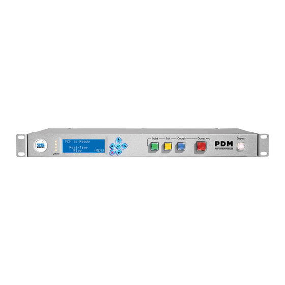
Page 23: Front Panel
The BUILD, EXIT, COUGH, and DUMP buttons are discussed starting on page The BYPASS button is used for emergencies or when you want to take PDM out of the signal chain . It connects PDM’s analog and digital inputs to its outputs, with no processing or delay. - Page 24 As the peak input signal increases between -36 dBFS and Full Scale, successive LEDs light up. All four LEDs will light yellow if PDM is expecting a Livewire input but not seeing a valid signal. This is usually a configuration problem. All four LEDs will also light yellow in the unlikely event of internal error, even on XLR (analog and AES/EBU) systems.
-
Page 25: Detailed Operating Instructions
This says the current time is 10:32 AM. PDM can display time in 12 or 24 10:32:00a This says the current time is 10:32 AM. PDM can display time in 12 or 24 hour modes; see hour modes. page 23. -
Page 26: General Menu Procedures
If you don’t press either button, the Confirmation screen times out after three minutes. Any changes you just made in the menu system are cancelled, and PDM returns to its normal You may also see a brief Waiting for audio stream message while PDM initializes its audio hardware. operating screen. -
Page 27: Pdm's Front Panel Menus
If you’re controlling PDM from a Web browser, most of the GUI versions of the menus If you’re controlling PDM from a Web browser, most of the GUI versions of the menus will will be virtually identical. The Web interface also includes extra configuration options will be virtually identical. - Page 28 Select a value between -10dBu and +20dBu to appear at the analog outputs, when PDM’s PDM’s internal digital signal level is 0 dBFS. This is usually set to match the Analog In- internal digital signal level is 0 dBFS. This is usually set to match the Analog Input sensitivi- put sensitivity, so our recommendation for most facilities would be 0dBFS = +14dBu.
- Page 29 This is to prevent operators from accidentally setting 1 and 20 unrealistic delays. Max Speed Sets a limit between 5 and 20% for how quickly PDM can build or exit a delay Build Mode Use to select what signal appears on PDM’s output (and is usually ¨...
- Page 30 30 | DETAILED OPERATING INSTRUCTIONS Build File Lets you choose which jingle or other audio file saved in PDM will play out when building a delay, if Insert has been selected in the menu above. to select the file’s name. PDM can store multiple audio files for flexibility in ¨...
- Page 31 PDM’s LCD display goes dark. Or choose Never, if you want the screen to remain lit at Use up/down arrows to change the character value, left/right arrows to change fields.
- Page 32 Disabling, pressing DONE, then re-enabling and pressing DONE will ask your system’s • Disabling, pressing DONE, then re-enabling and pressing DONE will ask your router to reset PDM’s IP address. It may take a few moments before a new address is registered.
- Page 33 The best way we have found to test whether NTP services are working is to manually offset your PDM clock by a couple of minutes, then enable NTP. If your network con- nections are working and your NTP address is valid, the system clock should quickly acquire the correct time.
- Page 34 Each of the 8 Inputs or outputs (e.g., In1, In2, Out1, Out2, etc) can be assigned to a Each of the 8 Inputs or outputs (e.g., In1, In2, Out1, Out2, etc) can be assigned to a PDM PDM function, as listed on the following chart. The same function can be assigned to Each of the 8 Inputs or outputs (e.g., In1, In2, Out1, Out2, etc) can be assigned to a...
- Page 35 Delay memory: pulse on Full FullTrig Delay memory: pulse on Empty EmptyTrig Build: mimic lamp state BuildLamp Exit: mimic lamp state ExitLamp Dump: mimic lamp state DumpLamp Cough: mimic lamp state CoughLamp PDM Operator's Manual Version 2.4a • September 2019...
- Page 36 Important notes about the table — Where an input function has the same name as a PDM front-panel button, the input behaves just like that button. For example, a momentary pulse on a GPIO Build input will start building the delay, just as if you’...
- Page 37 DETAILED OPERATING INSTRUCTIONS | 37 Connect this kind of contact closure or logic pulse to any PDM GPIO input that you’ve desig- nated as a Cue or Flag: when a signal is received, it’s linked to the incoming audio sample. It stays with this sample, no matter how much time manipulation is being applied.
- Page 38 The NTP Status display shows one of three messages, indicating the current connection with a remote time server: n Search PDM is seeking a path to the remote NTP server. If this message persists, it may indicate that the NTP server address you entered isn’t valid.
-
Page 39: Logging In To Pdm From A Connected Computer
PDM’s built-in port offset feature. The key is to forward pairs of port numbers. 18 This may be a setup issue in PDM’s menus or your local computer, a network wiring or configuration problem, or even something as simple as entering the IP address wrong in your browser. PDM responds to Ping commands as an aid for debugging. - Page 40 Flash movie control port will automatically be set to x –80 +5444. You don’t need to specify Flash ports, just which port your router uses to talk to PDM: if you set that and associated firewall permissions properly at the router, our software does the rest. ...
- Page 41 GUI AND WEB REMOTE CONTROL | 41 Front Panel GUI Page (Web Remote Control) You can operate PDM from this page, the same way you would from its hardware front panel, or use the pane to monitor LEDs and buttons.
- Page 42 You can control more than one PDM simultaneously from the same computer. All you need to know is each unit’s IP address, its user name, and its password (page 39). n Log in to any connected PDM, and click the second link at the bottom of the screen on the GUI: FRONT PANEL Click...
- Page 43 GUI AND WEB REMOTE CONTROL | 43 n PDM names (as set in the Configuration page) will be displayed at the top of each front panel, so you can identify specific units. These small front panels are displayed in the order you entered them. To change their...
- Page 44 GUI, and your browser changes to CONFIGURATION FRONT PANEL CONFIGURATION PD-ALERTS™ DUMP ARCHIVE AUDIO FILES INFORMATION look like this: Top part of Configuration page; there’s more on the next page of this manual. PDM Operator's Manual Version 2.4a • September 2019...
- Page 45 PDMs with Axia / Livewire software will have a few additional entries; see page 71 Changes that you enter on this page don’t take effect until you press the Save button on the bottom. PDM Operator's Manual Version 2.4a • September 2019...
- Page 46 46 | GUI AND WEB REMOTE CONTROL n If someone enters changes at PDM’s front panel while this GUI is open, the changes won’t be automatically reflected on your networked computer. You have to Refresh the page to see any the changes. To avoid confusion, don’t try to make configuration changes on both the GUI and PDM’s front panel at the same time.
-
Page 47: The Pd-Alert System
PDM. 20 PDM doesn’t receive e-mails; it only sends them. So it doesn’t need an incoming “POP” server. Also, PD-Alert does not support the SASL [Simple Authentication and Security Layer] protocol, so you won’t be able to use web mail services like Gmail. - Page 48 No matter which compression format you choose for e-mail audio files, PDM always keeps its internally stored files as full-resolution, uncompressed .WAV. 21 Assuming PDM is set for 8 second delay, 8 second dump increment, and 5 seconds each of before- and after-context.
- Page 49 If you want to enter more than one “text-only” recipient, separate each address with a space. Retain dump files: PDM purges old audio files to make room for new files when space is needed in its internal storage. There’s a lot of storage, so dump files can hang around for a long time.
- Page 50 The Date column includes the date and time that Alerts were sent. These entries are click- able: if you click an underlined date and time, PDM will display more details on the event, including links to the OnAir and OffAir audio dump files.
- Page 51 Dump files stored within DUMP ARCHIVE PDM, with the most recent ones on top. Files are built in pairs, one for the studio or telephone audio that got deleted (OffAir) and one for what listeners actually heard (OnAir).
- Page 52 The file pdm_demo_insert.wav is included for testing, and doesn’t have Delete or Rename buttons. 25 OnAir files are an exact copy of what gets sent to the transmitter. So if PDM was slowing down the audio after a dump to rebuild a delay, you’ll hear the effects of that expansion...
- Page 53 The file sample rate should match PDM’s internal sample clock: If your PDM is using only its analog inputs, it will run at 44.1 kHz and your files should be at that rate.
- Page 54 25-Seven’s identification numbers. Note that these settings may be changed only from the PDM front panel, not via the config- uration page. The page does not update automatically; refresh your browser if you need to see recent changes.
-
Page 55: Serial / Parallel Remote Control
Serial Control PDM’s serial control options let you build custom interfaces, such as for an on-air or logging systems. You can access PDM’s internal control language via RS-232 serial, a network Web browser, or both at the same time. - Page 56 ? Indicates command isn’t understood, or can’t be acted upon Output Events can be sent by PDM whenever there’s a change in status, such as memory being filled or buttons being pressed. They’re provided so you can design custom serial in- terfaces to other equipment.
- Page 57 Cues. A typical Output Event might look like: @DelaySafe=1<LF> Means Delay Safe is now on 29 That is, PDM’s memory now has enough audio to cover at least one complete dump. PDM Operator's Manual Version 2.4a • September 2019...
- Page 58 If you specify any command as the argument, it returns a brief explanation along with a list the command’s arguments. For example, if you send help down<LF>, PDM replies !down: send Press signal for one or more space-separated events (None Build Exit Cough Dump Bypass Cue1 …etc to…...
- Page 59 DelayEmpty Memory is empty DelayFull Delay is now full 30 xxxx is the serial number of that specific PDM. You can use this to verify the proper system is being accessed in facilities with multiple units. PDM Operator's Manual Version 2.4a • September 2019...
- Page 60 This command turns off reporting of one or more output events. It follows similar syntax. n disable DumpTrig<LF> tells PDM to stop reporting that DUMP has been activated. n disable DumpTrig Muted<LF> turns off reporting for both functions. n disable ALL<LF> turns off any message reporting.
- Page 61 SERIAL / PARALLEL REMOTE CONTROL | 61 Data Delays PDM can delay two data streams such as PAD (Program Associated Data), to keep it in sync with audio. This way, you can make sure “now playing” or other information on RDS receiv- ers or web streams lines up with program audio.
-
Page 62: Installation
| 62 Installation PDM fits a standard 19” equipment rack, 1 unit high by 12” deep (allow additional depth for the connectors). While PDM doesn’t generate much heat, we recommend at least one unit of blank or perfo- rated rack panel separating it from any heat-generating devices above or below it. Do not block the fan or intake vents on the rear of the unit. - Page 63 Whenever there’s a valid digital input signal at 44.1 kHz or 48 kHz, PDM locks its internal sample clock to it. This assures high quality and full compatibility with other other equipment in the facility, so you can use PDM as an analog-to-digital bridge.
- Page 64 64 | INSTALLATION n When PDM first powers up, it looks for a signal on its digital input jack. If it sees one at 48 kHz, it uses that sample rate to compute delay and ramping times. If it sees one at 44.1 kHz—or doesn’t see a valid digital signal at all—it uses 44.1 kHz.
- Page 65 Typical PDM remote input (left) and output (right) circuits. Use the jumpers shown in gray for simple pushbutton / LED remote. Or use just the opto-isolator connections without pins 8 and 20 for interface to other equipment.
- Page 66 Connecting to external logic or relay circuits: PDM’s GPIO inputs and outputs are isolated from its power supply and ground, and can be connected to external logic circuits or the power supplies in remote equipment: n Inputs require at least 6 mA flowing from the input common (pin 13) and the individual input circuit pin.
- Page 67 If you want to control it from a computer or dumb terminal, you’ll need a DB-25 null mo- dem or a cable that reverses pins 2 and 3 (data), pins 4 and 5 (flow control). Since PDM uses standard pin configurations, you should be able to use an easily available DB-25 to DB-9 adapter to connect more common 9 pin cables.
-
Page 68: Axia / Livewire Setup
For that reason, read the rest of this manual first. Then use this section to understand Livewire-specific setups. If you have an analog | AES/EBU version of PDM and wish to convert it to run as a Livewire device, please contact customer support. . - Page 69 32 “Ping” is a network diagnostic tool provided with almost all computers. each signal available on the Axia network 33 It may seem counter-intuitive to set up PDM’s input with a “Destination” channel. We did this to be consistent 00120 OK√...
- Page 70 PDM will treat that source as its input. address is valid. It may seem counter-intuitive to set up PDM’s input with a “Destination” channel. We did this to be consis- tent with other Axia equipment. Once you’ve set an address in this screen, PDM checks the network and makes sure the •...
- Page 71 PDM to communicate with. Devices are typically Element consoles with an Expert Monitor module, or Axia General Purpose Input/Output Nodes. n Input and Output selections for PDM Livewire GPIO are the same as for the PDM’s Hardware GPIO. See page 35 for a complete list.
- Page 72 In5=None Out5=DumpReady You also have to configure the console itself, so messages are properly sent to PDM. You’ll need a computer connected to the Livewire network, and a browser. From the web browser, enter the IP address of this particular console. This will take you to the Element Control Center page.
- Page 73 In our screen shot example, PDM’s Port Address 2 is set to communicate with port 4 of the GPIO Node at 192.168.1.21… In other words, if you pull Pin 11 (GPIO input 1) low on DB-15 number 4 (Port 4) on that node, PDM goes into Dump mode.
-
Page 74: Livewire Troubleshooting
Once you’re sure audio is being sent to PDM, the unit will start in Real-Time Play mode. Now you should be able to monitor PDM at its Source address (as set in the Axia Source screen), from other devices on the Axia network. Verify meter and monitor levels to and from the PDM at your Livewire node or control surface. -
Page 75: Software Updates And Factory Access
25-Seven Systems is constantly working to improve our products. Please check in with us for the latest software release information. Users running PDM version 1.5 or higher can self-install emailed versions of the latest firmware using a hidden, web-based utility from a networked computer. -
Page 76: Audio Specifications
THD @ 1 kHz = .025%; IMD (IHF) = .05% Frequency response = ±.5 dB 20 Hz – 20 kHz Measured in all modes, using analog connections; expect even better results with digital input and output. PDM Operator's Manual Version 2.4a • September 2019... -
Page 77: Warranty
| 77 Warranty Telos Alliance Limited Warranty For the latest Telos Alliance warranty, visit: telosalliance.com/warranty PDM Operator's Manual Version 2.4a • September 2019... - Page 79 Connect with 25-Seven Systems 1241 Superior Avenue Cleveland OH 44114 USA Main office: +1.216.241.7225 • 24/7 Tech Support: +1.216.622.0247 • Fax: +1.216.241.4103 • telosalliance.com © 2019 TLS Corp. The Telos Alliance.® All Rights Reserved. C19/14012 PN: 1490-00091-003---PDM CD OWNER'S MANUAL...
Need help?
Do you have a question about the PDM and is the answer not in the manual?
Questions and answers