Table of Contents
Advertisement
Quick Links
Installation, Operation & Maintenance Manual
Installation, Operation & Maintenance Manual
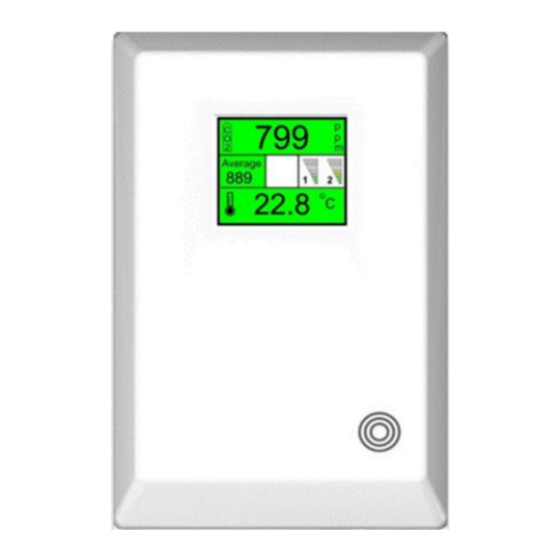
The Merlin CO2-TFT is designed to monitor carbon dioxide (CO
The monitor has a digital traffic light style display indicating the carbon dioxide levels and temperature in
the area. When CO
gas or temperature reaches alarm state – this device is able to automatically drive
2
ventilation fans reducing CO
The information contained within this manual should be referenced for typical installation and operation
only. For specific requirements that may deviate from the information in this guide – contact your supplier.
Rev 3 11-20
MERLIN CO2-TFT
Carbon Dioxide & Temperature Monitor
CO
measured and displayed in parts per million (PPM).
2
Temperature can be displayed in degrees Celsius (°C) or Fahrenheit (°F).
0-10V Signal Output progress bar display.
Monitor, record and display average CO
User friendly settings menu.
Pre-alarm and alarm relay output.
Fan controller enabled relay output.
Dual power 100-240VAC or 12-24V.
End of Life notification for CO
Automatically switch between ventilation programs when gas is used.
Boost, Mute and Wake Up button.
Please read this manual carefully and retain for future use.
and/or temperature.
2
concentration over 8 hour periods.
2
sensing element.
2
) in the air and temperature.
2
CO2-TFT
1
Advertisement
Table of Contents

Related Manuals for AGS MERLIN CO2-TFT


Summary of Contents for AGS MERLIN CO2-TFT
- Page 1 Installation, Operation & Maintenance Manual Please read this manual carefully and retain for future use. The Merlin CO2-TFT is designed to monitor carbon dioxide (CO ) in the air and temperature. The monitor has a digital traffic light style display indicating the carbon dioxide levels and temperature in the area.
- Page 2 Installation, Operation & Maintenance Manual CO2-TFT IMPORTANT WARNING STATEMENTS Please take the time to thoroughly read this user’s guide which should be retained for future reference. The expected lifetime of the gas sensor elements is 10 years upon initial power up. The device will display a message to indicate its end of life and should immediately be replaced.
-
Page 3: Table Of Contents
Installation, Operation & Maintenance Manual CO2-TFT CONTENTS INSTALLATION ................... 4 Planning ..........................4 Typical Positioning ........................ 4 Installation Arrangement ...................... 4 Fixing ............................5 Board Overview ........................5 Wiring your CO2-TFT ......................6 Configuration Settings ......................8 Menu Overview ........................8 Optional Configurations ...................... -
Page 4: Installation
Installation, Operation & Maintenance Manual CO2-TFT INSTALLATION Planning Area of coverage Consider the coverage required and function of the area. Emphasis should be placed on airflow patterns and correct placement, not perceived detecting ranges. The target gas will only be identified when contact is made with the sensing element itself. -
Page 5: Fixing
Installation, Operation & Maintenance Manual CO2-TFT Fixing Unpack all the parts! Designed for surface mounting, it must be installed by a licensed, insured contractor. 1. Carefully remove the rear cover from the unit by releasing the two latching clips located at the bottom of the case. -
Page 6: Wiring Your Co2-Tft
Installation, Operation & Maintenance Manual CO2-TFT Wiring your CO2-TFT MAINS POWER CONNECTION 100-120V AC Single phase mains power should be supplied to the [POWER/LINE IN] connector (Line & Neutral). The CO2-TFT can also be powered from 12-24V supply – see [12-24V POWER INPUT]. GAS VALVE INPUT It is possible for your CO2-TFT to receive a signal from a gas solenoid valve via Live &... - Page 7 Installation, Operation & Maintenance Manual CO2-TFT CO2 PRE-ALARM This relay can send a signal to a Building Management System (BMS) or Merlin panel when CO reaches pre-alarm level. FAN ENABLE The [FAN ENABLE] relay output can be connected to a fan switch which can energise fans via a signal.
-
Page 8: Configuration Settings
Installation, Operation & Maintenance Manual CO2-TFT Configuration Settings There is a settings switch on the CO2-TFT board. Switch it on to prompt the on-screen menu. Navigate the menu using the buttons on the board. When changes have been made – turn the settings switch off. [SEL.] button [OK] button Scroll through functions (highlighted red). -
Page 9: Optional Configurations
Installation, Operation & Maintenance Manual CO2-TFT Optional Configurations NAT. - Natural Ventilation Mode Green: <1300ppm <23 °C/ 73.4°F 0-10V Analogue Output: Linear Progression. Yellow: >1300ppm >23 °C/ 73.4°F Min output (1-5V) from 600ppm 23 °C/ 73.4°F Max output (10V) from 1500ppm 27 °C/ 80.6°F Red: >1500ppm >25 °C/ 77.0°F Pre-alarm relay switch: 1300ppm... -
Page 10: Factory Set Condition
Installation, Operation & Maintenance Manual CO2-TFT Factory Set Condition KITCH. VENT. TYPE BUZZER SCREEN SAVER °C MIN 0-10 OUT 1 TEMP. UNITS MIN 0-10 OUT 2 BOOST (MIN.) TEMP 0-10V OUT 1 FAN ENABLE 0-10V OUT 2 BRIGHTNESS FACTORY RESET Specification Product: Dual Power Carbon Dioxide &... -
Page 11: Operation
Installation, Operation & Maintenance Manual CO2-TFT OPERATION First Power Up On connecting power, the CO2-TFT monitor enters a stabilisation phase for approximately 60 seconds – during this period, your device not yet ready for operation. a. CARBON DIOXIDE READING. Current CO gas level in parts per million (ppm). -
Page 12: Traffic Light Indicator
Installation, Operation & Maintenance Manual CO2-TFT Traffic Light Indicator Your CO2-TFT displays both current CO and temperature levels in a traffic light style indication. ATTENTION! SAFE DANGER! Low CO levels or temperature Safe CO levels or temperature High CO levels or temperature will be displayed GREEN. -
Page 13: Screen Saver Mode
Installation, Operation & Maintenance Manual CO2-TFT Screen Saver Mode If the screen saver mode is switched on (see settings), the CO2-TFT monitor screen will switch off when both CO and Temperature levels are at safe levels (green). No readings or messages will be visible during this time. -
Page 14: Maintenance
Installation, Operation & Maintenance Manual CO2-TFT MAINTENANCE Cleaning Keep your detector in good working order follow these basic principles; Carefully remove any accumulated dust from the outer enclosure using a slightly damp cloth. Never use detergents or solvents to clean your device – this may permenantly or temporarily ... -
Page 15: Notes (Blank)
Installation, Operation & Maintenance Manual CO2-TFT Notes (blank) Rev 3 11-20... -
Page 16: Installation Details
Installation, Operation & Maintenance Manual CO2-TFT Installation Details Please pass this manual to the system owner / user. Date of Installation: Installation Location: Organisation: Stamp/ Signature of the installer: Replacement Date: American Gas Safety LLC Head office: 6304 Benjamin Road, Suite 502, Tampa, FL 33634 Tel: (727) 608-4375 info@americangassafety.com American Gas Safety LLC is the owner of this document and reserves all rights of modification without prior notice.
Need help?
Do you have a question about the MERLIN CO2-TFT and is the answer not in the manual?
Questions and answers