
Related Manuals for Orbit Merret OMD 202RS


Summary of Contents for Orbit Merret OMD 202RS
- Page 1 USER MANUAL OMD 202RS - MB 4/6 DIGIT PROGRAMMABLE LARGE DISPLAY DATA DISPLAY RS 232/485 MODBUS WA R R A N T Y Y E A R S...
- Page 2 The recorders are applicable for unlimited use in agricultural and industrial areas. ORBIT MERRET, spol. s r.o. Vodnanska 675/30 198 00 Prague 9 Czech Republic Tel: +420 - 281 040 200 Fax: +420 - 281 040 299 e-mail: orbit@merret.eu www.orbit.merret.eu 2 | INSTRUCTIONS FOR USE OMD 202RS...
-
Page 3: Table Of Contents
6.3.3 Setting analog output ....62 6.3.4 Selection of display projection ... . 63 INSTRUCTIONS FOR USE OMD 202RS | 3... -
Page 4: Instrument Description
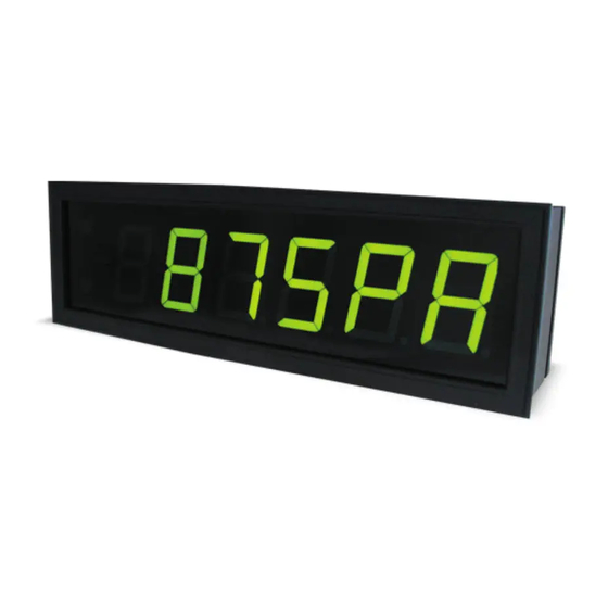
2. INSTRUMENT DESCRIPTION DESCRIPTION The OMD 202RS model series are 4/6 digit large panel programmable displays for the projection of data from data lines RS 232, RS 485 in protocoles ASCII/MESSBUS/MODBUS/PROFIBUS. The instrument can be supplied with either a 3-colour LED display (red/green/orange) or with hight intensity SMD LEDs (red or green with brightness of 1 300 mcd). - Page 5 PC. It is manufactured in version RS 232 and USB and is compatible with all ORBIT MERRET instruments. Another option for connection is with the aid of data output RS 232 or RS 485 (without the need of the OML cable).
-
Page 6: Instrument Connection
Provided this cannot be secured it is necessary to use shielded leads with connection to ground (bracket E). The instruments are tested in compliance with standards for use in industrial area, yet we recommend to abide by the above mentioned principles. 6 | INSTRUCTIONS FOR USE OMD 202RS... - Page 7 INSTRUMENT CONNECTION FUSE INSTRUCTIONS FOR USE OMD 202RS | 7...
-
Page 8: Instrument Setting
Linear menu structure SETTING USER For user operation Menu items are set by the user (Profi/Light) as per request Access is not password protected Optional menu structure either tree (PROFI) or linear (LIGHT) 8 | INSTRUCTIONS FOR USE OMD 202RS... - Page 9 The operation program is freely accessible (www.orbit.merret.cz) and the only requirement is the purchase of OML cable to connect the instrument to PC. It is manufactured in version RS 232 and USB and is compatible with all ORBIT MERRET instruments.
-
Page 10: Symbols Used In The Instructions
Setting the minus sign is performed by the key on higher decade. When editing the item substraction must be made from the current number (e.g..: 013 > , on class 100 > -87) 10 | INSTRUCTIONS FOR USE OMD 202RS... -
Page 11: Control Keys Function
SHOW item will not be displayed in USER menu item will be displayed in USER menu with the option of setting SHOW item will be solely displayed in USER menu INSTRUCTIONS FOR USE OMD 202RS | 11... -
Page 12: Setting "Light" Menu
Preset from manufacture Password “0” Menu LIGHT USER menu Setting the items Upon delay exceeding 60 s the program- ming mode is automatically discontinued and the instrument itself restores the me- asuring mode 12 | INSTRUCTIONS FOR USE OMD 202RS... - Page 13 Return to manufacture setting Language selection COL. 2 MENU LIGHT RE. SET. FIRM. LANG. ENGL. New password Instrument type Identifi cation SW number Return to measuring PAS. LI. IDENT. OMD202RS 142. 8 mode INSTRUCTIONS FOR USE OMD 202RS | 13...
- Page 14 = 9 600 Baud - selection of range: 600/1 200/2 400/9 600/ 19 200/38 400/57 600/115 200/230 400 Baud Selection of rate 115200 Baud > BAUD = 115200 Example 9600 19200 38400 57600 ADDR. 14 | INSTRUCTIONS FOR USE OMD 202RS...
- Page 15 Instrument solicits data by selected command from given register SLAVE Display shows data entered through commands 0x06 nebo 0x10 Data protocol = SLAVE > SLAVE Example ASCII COMMAN. * subsequent item on the menu depends on instrument setting INSTRUCTIONS FOR USE OMD 202RS | 15...
- Page 16 - range of setting 0…65 535 - the address usually entered is 0…9999 (without highest digit) - defines address of the register to be read Register address 3 > REG. = 1 Example MO. T . O . 16 | INSTRUCTIONS FOR USE OMD 202RS...
- Page 17 Mod t.0. - range: 0…99,9 s Setting - Constant > tIMEOU. = 1 Example 1. 0 FORMAT Item will not appear in MASTER protocol and when MOD t.0. is disabled INSTRUCTIONS FOR USE OMD 202RS | 17...
- Page 18 <AA> 10 00 00 00 02 04 <Hi Word Hi> <Hi Word Lo> <Lo Word Hi> <Lo Word Lo> <CRC Lo> <CRC Hi> LEGEND SIGN DESCRIPTION Beginning of command <AA> Instrument address (1…247) <Word xx> 16-bit data <Lo Word xx> 32-bit data (lower part) <Hi Word xx> 32-bit data (higher part) 18 | INSTRUCTIONS FOR USE OMD 202RS...
- Page 19 - range of setting 0…65 535 = 32 767 (S.INT.16) Setting for maximum “Lo” > MAX. LO. = 62135 Example 65535 65535 65535 65435 65335 65235 65135 65135 64135 63135 62135 MIN A INSTRUCTIONS FOR USE OMD 202RS | 19...
- Page 20 = 0 (U.INT.32) - range of setting -99999…99999 = 32768 (S.INT.32) - preset value in HEX format equals 0x800 0000 Setting for minimum “Lo” > Min. LO. = 0 Example MAx . LO 20 | INSTRUCTIONS FOR USE OMD 202RS...
- Page 21 - preset value in HEX format equals 0x7FFF FFFF Setting for maximum “Lo” > MAX. LO. = 62135 Example 65535 65535 65535 65435 65335 65235 65135 65135 64135 63135 62135 MIN A INSTRUCTIONS FOR USE OMD 202RS | 21...
- Page 22 Setting for minimum > Min = 0 Example Setting minimum input value Setting maximum value of input data - range of setting -99999…99999 = 100 Setting for maximum > MAX = 300 Example MIN A 22 | INSTRUCTIONS FOR USE OMD 202RS...
- Page 23 - position of the DP does not affect display projection - the DP is automatically shifted after the value is confirmed Projection for max > MAX A = 100.00 Example 100. 0 FORM. A INSTRUCTIONS FOR USE OMD 202RS | 23...
- Page 24 - positioning of the DP is set here in the measuring mode Projection of DP on display > 00000.o Example 0000. o o 00000. o COL. 0 *subsequent item on the menu depends on instrument equipment 24 | INSTRUCTIONS FOR USE OMD 202RS...
- Page 25 SETTING LIGHT 5. INSTRUCTIONS FOR USE OMD 202RS | 25...
- Page 26 Setting limit 2 > LIM. L.2 = 53.1 Example 0531 00531 000531 000531. 00053. COL. 0 * subsequent item on the menu depends on instrument equipment Items for “Limits” and “Analog output” are accessible only if incorporated in the instrument. 26 | INSTRUCTIONS FOR USE OMD 202RS...
- Page 27 - contingent modification of hysteresis or delay Hysteresis „ ”=0, „Delay”=0 may be performed in “PROFI” menu Setting limit 4 > LIM. L.4 = 103 Example COL. 0 * subsequent item on the menu depends on instrument equipment INSTRUCTIONS FOR USE OMD 202RS | 27...
- Page 28 Display value for the beginning of the AO range > MIN A.O. = 0 Example MAX A. O . Items for “Limits” and “Analog output” are accessible only if incorporated in the instrument. 28 | INSTRUCTIONS FOR USE OMD 202RS...
- Page 29 Assigning the display value to the end of the AO range - range of the setting: -99999…999999 = 100 Display value for the end of the AO range > MAX A.O. = 120 Example COL. 0 INSTRUCTIONS FOR USE OMD 202RS | 29...
- Page 30 - the color changes if the displayed value is higher than the value set in dIS. L.1 Selection of display color if the data is > COL. 1 = green Example ORANGE GREEN DIS. L. 2 30 | INSTRUCTIONS FOR USE OMD 202RS...
- Page 31 - the color changes if the displayed value is higher than the value set in dIS. L.2 Selection of display color if the data is > COL. 2 = orange Example ORANGE ADR. IR. INSTRUCTIONS FOR USE OMD 202RS | 31...
- Page 32 > tree menu structure > linear tree structure = LIGHT Menu LIGHT > MENU = LIGHT Example LIGHT RE. SET. 32 | INSTRUCTIONS FOR USE OMD 202RS...
- Page 33 - by saving the user user setting it is possible to recall it later without the need of going through the customisation process again Saving the user setting > SAVE Example SAVE PAS. LI. INSTRUCTIONS FOR USE OMD 202RS | 33...
- Page 34 - range of the number code 0…9999 - upon setting the password to “000” the access to menu LIGHT is free without prompt to enter it New password - 341 > PAS. LI. = 341 Example IDENT. 34 | INSTRUCTIONS FOR USE OMD 202RS...
- Page 35 - after the identification is completed the menu is input setting (Mode) automatically exited and the instrument restores the measuring mode - if SW version contains a letter in first position, 142. 8 Return to measuring mode INSTRUCTIONS FOR USE OMD 202RS | 35...
- Page 36 • password protected access (unless set as follows under the item SERVIC. > N. PASS. > LIGHT =0) • for access to LIGHT menu passwords for LIGHT and PROFI menu may be used 36 | INSTRUCTIONS FOR USE OMD 202RS...
- Page 37 SETTING PROFI INSTRUCTIONS FOR USE OMD 202RS | 37...
- Page 38 CHANNE. CONFIG CL. M. M . OUTPUT. EXT. IN. CL. M. M . Resetting min/max value SERVIC. KEYS - resetting memory for the storage of minimum and maximum value achieved during measurement 38 | INSTRUCTIONS FOR USE OMD 202RS...
- Page 39 ADDR. Setting instrument address INPUTS CLEAR BAUD - setting in range: 0…31 = 00 CHANNE. CONFIG. ADDR. OUTPUT. EXT. IN. PROT. SERVIC. KEYS COMMAN. . REGIST. MOD. T. 0 TIMEOU. FORMAT ORDER INSTRUCTIONS FOR USE OMD 202RS | 39...
- Page 40 DISPL. D. +A. O . D. + A. O . . + L. ALL KEYS LEFT FN. LE. NO TMP. LE. NO ENTER MNU. LE. LIM. 1 40 | INSTRUCTIONS FOR USE OMD 202RS...
- Page 41 RED GREEN ORANGE BRIGHT 0% 25% 50% 75% 100% Upon delay exceeding 60 s the program- ming mode is automatically discontinued and the instrument itself restores the me- asuring mode INSTRUCTIONS FOR USE OMD 202RS | 41...
- Page 42 PROT. registers at address 4xxxx SERVIC. KEYS COMMAN. COM. 0 4 Reading input (input) registers at address 3xxxx REGIST. MOD. T. 0 TIMEOU. Item will appear only in “MASTER” protocol FORMAT ORDER 42 | INSTRUCTIONS FOR USE OMD 202RS...
- Page 43 COMMAN. DASHES. FLASH Last displayed value starts REGIST. flashing MOD. T. O DASHES Dash symbols displayed TIMEOU. Decimal point is displayed FORMAT ORDER Item will not appear in “MASTER” protocol INSTRUCTIONS FOR USE OMD 202RS | 43...
- Page 44 S. I NT. 3 2 32-bit sign integer TIMEOU. FORMAT - range: -2 147 483 648…2 147 483 644 FLOAT IEEE format ORDER - range: ±6,80564693277058E+38 - for description see table on page 72 44 | INSTRUCTIONS FOR USE OMD 202RS...
- Page 45 Lower 16 bit is transmitted first CHANNE. CONFIG. ADDR. . HI-LO HI-LO Higher 16 bit is transmitted OUTPUT. EXT. IN. PROT. second SERVIC. KEYS COMMAN. REGIST. MOD. T. O TIMEOU. FORMAT ORDER INSTRUCTIONS FOR USE OMD 202RS | 45...
- Page 46 = 32 767 (S.INT.32) TIMEOU. „FORMAT“ > FLOAT FORMAT - range of the setting: -99 999…999 999 ORDER Setting mimum value of input data MIN. MAX. Setting maximum value of input data = 100 46 | INSTRUCTIONS FOR USE OMD 202RS...
- Page 47 SETTING PROFI INSTRUCTIONS FOR USE OMD 202RS | 47...
- Page 48 D. + A. O . + L. “HOLD” locks the value SERVIC. KEYS M. HOLD displayed, on AO and limit evaluation “HOLD” locks the entire instrument Setting procedure is identical for EXT. 2 and EXT. 3 48 | INSTRUCTIONS FOR USE OMD 202RS...
- Page 49 TARE Tare function activation Preset values of the control keys LEFT Show Tare Show max. value DOWN Show min. value Setting is identical for LEFT, DOWN, UP and ENTER w/o function ENTER INSTRUCTIONS FOR USE OMD 202RS | 49...
- Page 50 LIM. 4 Temporary projection of “Limit 4” value TARE Temporary projection of “TARE” value P. TARE Temporary projection of “P. TARE” value Setting is identical for LEFT, DOWN, UP and ENTER 50 | INSTRUCTIONS FOR USE OMD 202RS...
- Page 51 Direct access to item “OFF L.2” OFF 3 Direct access to item “OFF L.3” OFF 4 Direct access to item “OFF L.4” Setting is identical for LEFT, DOWN, UP and ENTER INSTRUCTIONS FOR USE OMD 202RS | 51...
- Page 52 - when setting (P. TAR.A ≠ 0) display shows “T” OUTPUT. MIN. M AX. FORM. A P. T AR. A symbol - range of the setting: -99999…999999 SERVIC. DESC. A 52 | INSTRUCTIONS FOR USE OMD 202RS...
- Page 53 (e.g.: „CON.F. A“ = 2.5 > display 0, 2.5, 5,...) Floating filter Constant F.A = 5.0 CON. F. A Setting constants - this menu item is always displayed after selection of particular type of filter Exponential filter Constant F.A = 5.0 INSTRUCTIONS FOR USE OMD 202RS | 53...
- Page 54 0…95 SERVIC. DESC. A - description is cancelled by code 00 = no description Table of signs on page 75 54 | INSTRUCTIONS FOR USE OMD 202RS...
- Page 55 Power ROOt Root SIN X Sin x sinx CON. - Setting constants for calculation of mat. functions - this menu is displayed only after selection of given mathematic function INSTRUCTIONS FOR USE OMD 202RS | 55...
- Page 56 0…95 SERVIC. CON. C - description is cancelled by code 00 = no description CON. D CON. E CON. F Table of signs on page 75 FORM. M. DESC. M. 56 | INSTRUCTIONS FOR USE OMD 202RS...
- Page 57 Evaluation of min/max OUTPUT. MIN. M AX. FIL. A value is off SERVIC. MAT. FN. CHAN. A From “Channel A” FIL. A From “Channel A” after digital filters processing MAT. FN. From “Mathematic functions” INSTRUCTIONS FOR USE OMD 202RS | 57...
- Page 58 OFF L. 1 “Mathematic functions” Limit evaluation from PER. L. 1 “Min.value” TIM. L. 1 Limit evaluation from “Max. value” Setting is identical for LIM 1, LIM 2, LIM 3 and LIM 4 58 | INSTRUCTIONS FOR USE OMD 202RS...
- Page 59 Z < 0 - Switch-on relay TYPE > SWITCH-OFF LED signalization Z > 0 - Switch-off relay TYPE > SWITCH-ON LED signalization Z < 0 - Switch-off relay TYPE > SWITCH-OFF LED signalization INSTRUCTIONS FOR USE OMD 202RS | 59...
- Page 60 LIM 4 LIM. L. 1 HYS. L. 1 Setting is identical for LIM 1, LIM 2, LIM 3 and LIM 4 ON L. 1 OFF L. 1 PER. L. 1 TIM. L. 1 60 | INSTRUCTIONS FOR USE OMD 202RS...
- Page 61 - negative time > relay switches off after crossing the limit (LIM. L.1) and the set negative time (TIM. L.1) Setting is identical for LIM 1, LIM 2, LIM 3 and LIM 4 INSTRUCTIONS FOR USE OMD 202RS | 61...
- Page 62 0-2V 0-5V 0-5mA Type: 0…5 mA 0- 10V 0-2V Type: 0…2 V +- 10V 0-5V Type: 0…5 V 0- 10V Type: 0…10 V +- 10V Type: ±10 V 62 | INSTRUCTIONS FOR USE OMD 202RS...
-
Page 63: Setting Analog Output
- data which have been succesfully converted to numbers will be projected MAT. FN. Projection of values from “Math. functions” Projection of values from “Min. value” Projection of values from “Max. value” INSTRUCTIONS FOR USE OMD 202RS | 63... - Page 64 DIS. L. 1 - “DIS. L.1” = 33.33 SERVIC. DISP. COL. 1 - “DIS. L.2” = 66.67 DIS. L. 2 COL. 2 Not aplicable to the version with monocolur high brightness LED display BRIGHT 64 | INSTRUCTIONS FOR USE OMD 202RS...
- Page 65 - after keystroke display turns on for 10 s DIS. L. 2 Display brightness - 25 % COL. 2 Display brightness - 50 % BRIGHT Display brightness - 75 % 100% Display brightness - 100 % INSTRUCTIONS FOR USE OMD 202RS | 65...
-
Page 66: Setting The Address Of Ir Remote Control
LED lights up on the display - then you can control the dispaly in the standard way in LIGHT/PROFI/USER menu - if needed, the address can cancelled by pressing the blue button of the remote 66 | INSTRUCTIONS FOR USE OMD 202RS... -
Page 67: Restoration Manufacture Setting
SERVIC./RESTOR/SAVE SAVE Save instrument user setting - storing the user setting allows the operator to restore it in future if needed After restoration the instrument switches off for couple seconds INSTRUCTIONS FOR USE OMD 202RS | 67... -
Page 68: Selection Of Instrument Menu Language Version
- if the SW version reads a letter on first position, it is a customer SW CHANNE. MENU OUTPUT. RESTOR. Blok Description Instrument SERVIC. LANG. no. of SW version N. PASS. type/input mode IDENT. 68 | INSTRUCTIONS FOR USE OMD 202RS... - Page 69 SETTING PROFI INSTRUCTIONS FOR USE OMD 202RS | 69...
-
Page 70: Setting Items Into "User" Menu
SHOW item will not be displayed in USER menu item will be displayed in USER menu with the option of setting SHOW item will be solely displayed in USER menu 70 | INSTRUCTIONS FOR USE OMD 202RS... - Page 71 „LIM. L.2“ where you repeat the procedure. You can finish the setting up by pressing the button, by which you save the latest setting and by pressing the you return to the operating mode. INSTRUCTIONS FOR USE OMD 202RS | 71...
-
Page 72: Data Protocol
<AA> 20 <number of characters in standard message> standard message <CRC Lo> <CRC Hi> In this format is also the response ?00, reporting error in processing standard OM command. Address field of standard message will always be 00 - here without any significance. 72 | INSTRUCTIONS FOR USE OMD 202RS... - Page 73 IEEE fl oating point Z…sign (1(0)/-1(1)); E…Exponent (-127(0x00)…0(0x7F)…128(0xFF)) M…Mantisa (1.0…2.0), highest mantisa bit is always 1 and it is covered by the lowest exponent bit e.g.: 0x3F80 0000 = Z*2ˆE*M = 1*2ˆ(0)*1 = 1 INSTRUCTIONS FOR USE OMD 202RS | 73...
-
Page 74: Error Statements
E. CLR. upon repeated error statement send instrument for repair, Memory was empty (presetting carried out) possible failure in calibration E. . OUT. Analogue output current loop disconnected check wire connection 74 | INSTRUCTIONS FOR USE OMD 202RS... - Page 75 Description is cancelled by entering characters with code 00 " & " & < > < > Table ASCII STX ETX EOT ENQ ACK BEL DLE DC1 „ & ‚ < > INSTRUCTIONS FOR USE OMD 202RS | 75...
-
Page 76: Technical Data
1/8 HP 277 VAC, 1/10 HP 125 V, Pilot Duty instrum.power supply > 670 V (PI), 300 V (DI) D300 Input/output > 300 V (PI), 150 (DI) EMC: EN 61326-1 * values apply for resistance load PI - Primary insulation, DI - Double insulation 76 | INSTRUCTIONS FOR USE OMD 202RS... -
Page 77: Instrument Dimensions And Instalation
X1 mm Panel thickness: 0,5 ... 50 mm Height 57-6 100-4 100-6 125-4 125-6 Wall mounting Our large displays are supplied along with a wall mount holder as shown in the the drawing. INSTRUCTIONS FOR USE OMD 202RS | 77... -
Page 78: Certificate Of Guarantee
- other unprofessional interventions other u entions The manufacturer performs guarantee and post.guarantee repairs unless provided for otherwise. erforms guarantee and po ss provided for oth Y E A R S Stamp, signature 78 | INSTRUCTIONS FOR USE OMD 202RS... - Page 79 ORBIT MERRET, spol.s r.o. and that our company has taken all measures to ensure conformity of all products of the types referred-to hereunder, which are being brought out to the market, with technical documentation and requirements of the appurtenant Czech statutory orders.
- Page 80 ORBIT MERRET, spol. s r. o. Vodňanská 675/30 198 00 Praha 9 Czech Republic tel.: +420 281 040 200 fax.: +420 281 040 299 e-mail: orbit@merret.eu www.orbit.merret.eu TECHDOK - OMD 202RS - MODBUS - 2018 - 4v0 - en...
Need help?
Do you have a question about the OMD 202RS and is the answer not in the manual?
Questions and answers